
In my extensive experience within the heavy machinery and power generation sectors, I have frequently encountered the challenge of repairing cracks in large gray iron shell castings. These shell castings, often made from materials like HT250, are critical components in equipment such as turbine casings, pump housings, and compressor bodies. Their complex geometries and substantial wall thicknesses make them prone to stress-induced cracking during casting or under operational loads, leading to leaks and potential failures. Traditional repair methods, particularly welding, are fraught with difficulties, including high residual stresses, secondary cracking, and the need for extensive pre- and post-heat treatments. These limitations are especially problematic for on-site repairs where disassembly is impractical. This article details an alternative approach I have successfully employed: a non-welding suture repair technique that utilizes specialized screws and reinforcement locks to mechanically stitch cracks without thermal input. This method not only preserves the integrity of the shell castings but also facilitates rapid, on-site restoration with minimal downtime.
The prevalence of gray iron in shell castings stems from its excellent castability, damping capacity, and cost-effectiveness. However, its relatively low ductility and tensile strength make it susceptible to crack initiation and propagation, particularly in areas of geometric discontinuity or high stress concentration. Cracks in these shell castings often manifest as irregular, radiating, and sometimes through-thickness fissures, typically relaxing the internal stresses once they occur. When such defects arise in critical equipment—like a large turbine casing operating at temperatures up to 180°C and pressures around 0.3 MPa—the immediate concern is to restore structural integrity and leak-tightness without exacerbating the problem. The suture repair method addresses this by providing a mechanical interlock that bridges the crack, preventing further extension and restoring pressure boundary integrity.
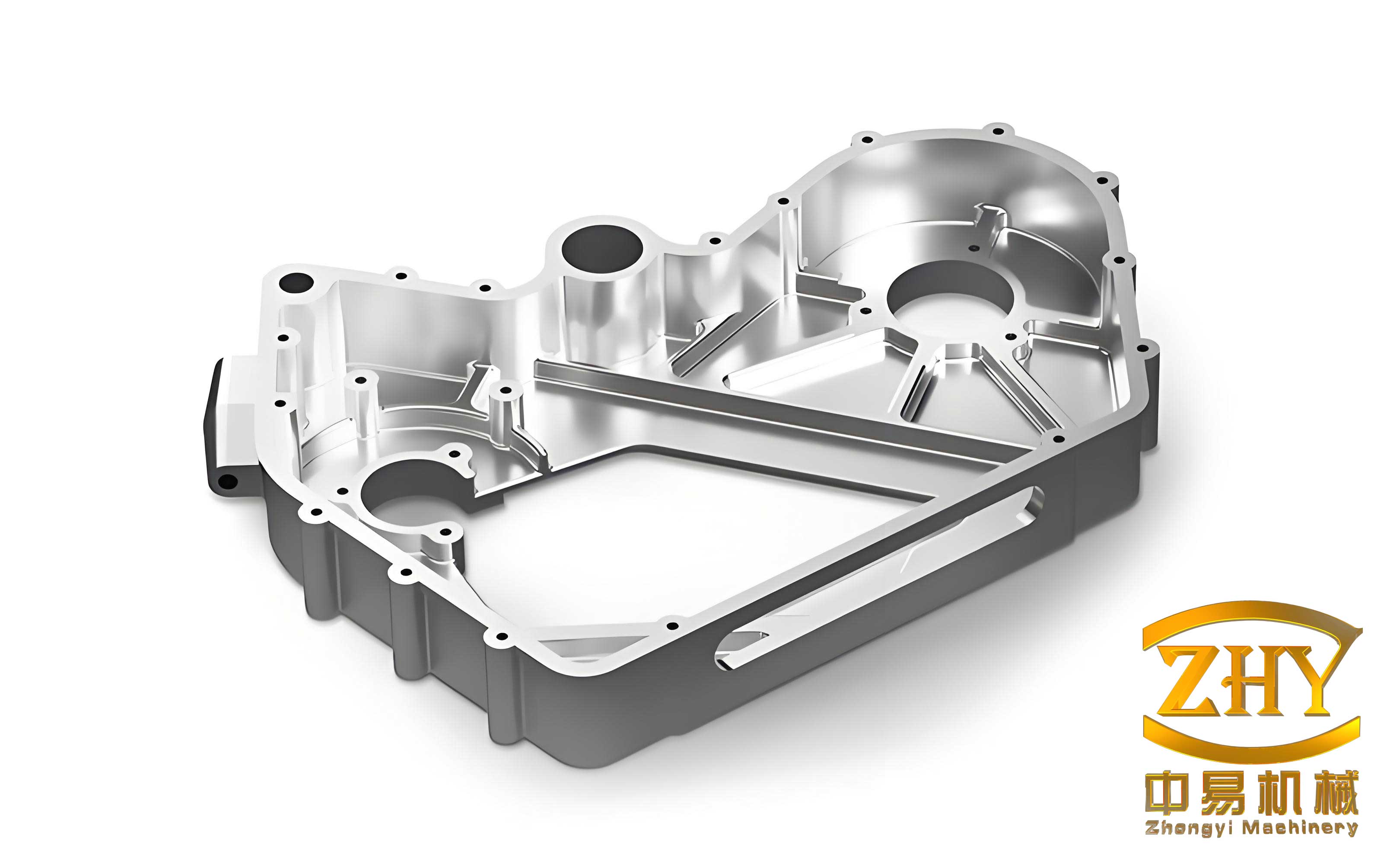
The fundamental principle behind suture repair is to transfer loads across the crack face through a series of threaded fasteners and reinforcement elements, effectively creating a mechanical bond. This approach leverages the fact that gray iron, while poor in tension, exhibits good compressive strength. By installing components that clamp the crack faces together, we induce a state of compression along the crack path, thereby inhibiting opening modes. The key components are custom-made screws and reinforcement locks, both designed to match the material properties of the shell castings to avoid galvanic corrosion or differential thermal expansion issues. The process involves drilling, tapping, and installing these elements in a staggered pattern along the crack, followed by the insertion of reinforcement locks perpendicular to the crack line to distribute stresses and provide additional restraint.
To understand the mechanical basis, consider the stress state near a crack tip. The stress intensity factor, \( K_I \), for Mode I (opening) cracking is given by:
$$ K_I = Y \sigma \sqrt{\pi a} $$
where \( \sigma \) is the applied stress, \( a \) is the crack length, and \( Y \) is a geometric factor. For a through-crack in a plate, \( Y \) approximates 1. The suture repair aims to reduce the effective \( \sigma \) at the crack tip by introducing closure forces. Each screw applies a clamping force, \( F_c \), which generates a compressive stress, \( \sigma_c \), over an area \( A_c \). The net stress driving crack propagation becomes:
$$ \sigma_{\text{net}} = \sigma – \sigma_c = \sigma – \frac{F_c}{A_c} $$
If \( \sigma_{\text{net}} \) falls below the threshold stress intensity, \( K_{I\text{th}} \), for gray iron, crack arrest is achieved. For HT250, typical threshold values range from 6 to 10 MPa√m, depending on microstructure and loading conditions.
The selection of screw and lock parameters is critical. The screws are made from a material with similar hardness, thermal expansion coefficient, and corrosion resistance as the base iron—often a high-strength aluminum alloy or a specially treated steel. Their thread profile is optimized for engagement in gray iron, which has lower shear strength than ductile metals. The pull-out strength of a threaded fastener in gray iron can be estimated using:
$$ F_{\text{pull-out}} = \tau_s \cdot A_s $$
where \( \tau_s \) is the shear strength of the iron (approximately 0.6 times the tensile strength for gray iron) and \( A_s \) is the effective shear area of the threads. For a coarse thread M10 screw in HT250 (tensile strength ~250 MPa), \( \tau_s \approx 150 \) MPa. If the engaged length is 50 mm in a 60 mm thick wall, the shear area per pitch is:
$$ A_s = \pi \cdot d \cdot L_e $$
where \( d \) is the nominal diameter (10 mm) and \( L_e \) is the engagement length (50 mm). Thus:
$$ A_s = \pi \times 10 \times 50 = 1570.8 \, \text{mm}^2 $$
$$ F_{\text{pull-out}} = 150 \times 1570.8 = 235.62 \, \text{kN} $$
This far exceeds the operational stresses, ensuring a robust fix.
The repair process begins with a thorough inspection to map the crack. Dye penetrant testing is employed to reveal the full extent, including secondary micro-cracks. The crack path is marked, and its termini are identified to plan for stop-drill holes. The following table summarizes the key steps and tools involved in the suture repair procedure:
| Step | Description | Tools Required | Key Parameters |
|---|---|---|---|
| 1. Crack Mapping | Apply dye penetrant, clean, and mark crack with emphasis on ends. | Dye penetrant kit, cleaning solvents, scribe. | Crack length \( L_c \), orientation. |
| 2. Stop-Drilling | Drill holes at crack termini to relieve stress and prevent propagation. | Hand drill, Ø8 mm drill bit, depth gauge. | Hole depth: 20 mm, diameter: 8 mm. |
| 3. Drill Jig Setup | Mount drilling templates for screw holes and lock slots. | Custom drill jigs, clamping fixtures. | Hole spacing: 1.5 × screw diameter (15 mm for M10). |
| 4. Screw Hole Drilling | Drill staggered holes along crack midline to 90% of wall thickness. | Hand drill, Ø8.5 mm drill bit (for M10 tap). | Depth: 55 mm for 60 mm wall. |
| 5. Tapping | Cut M10 threads in holes using coarse-pitch tap. | M10 tap, tap wrench, cutting fluid. | Thread depth: 50 mm. |
| 6. Counterboring | Enlarge hole entrance to Ø12 mm for screw head seating. | Ø12 mm drill bit, depth stop. | Counterbore depth: 8 mm. |
| 7. Screw Installation | Insert custom screws, tighten, cut excess, peen, and grind flush. | Torque wrench, hacksaw, ball-peen hammer, grinder. | Torque: 20-30 Nm for M10 aluminum screw. |
| 8. Lock Slot Machining | Drill slots perpendicular to crack for reinforcement locks. | Slotting drill jig, end mill or series drill. | Slot spacing: 20 mm, depth: lock thickness. |
| 9. Lock Installation | Press-fit locks into slots, peen edges, grind smooth. | Hammer, drift punch, grinder. | Interference fit: 0.05-0.10 mm. |
| 10. Finishing & Inspection | Grind entire area smooth, perform dye penetrant and pressure tests. | Grinder, dye penetrant, pressure pump. | Surface roughness: Ra ≤ 12.5 µm. |
The custom screws are designed with a unique thread profile to maximize load transfer in gray iron. Their mechanical properties are chosen to match those of the shell castings. The following table compares the typical properties of HT250 gray iron with the aluminum alloy used for screws:
| Property | HT250 Gray Iron | Aluminum Alloy (e.g., 7075-T6) | Remarks |
|---|---|---|---|
| Tensile Strength | 250 MPa | 570 MPa | Screw stronger to ensure no failure. |
| Yield Strength | – (≈ 250 MPa) | 505 MPa | Gray iron yields abruptly. |
| Elongation | < 1% | 11% | Screw more ductile. |
| Young’s Modulus | 110 GPa | 71 GPa | Lower modulus reduces stress concentration. |
| Thermal Expansion | 11 × 10-6 /°C | 23.6 × 10⁻⁶ /°C | Mismatch managed via design. |
| Hardness (Brinell) | 180-250 HB | 150 HB | Similar to avoid embedding. |
The reinforcement locks, typically made from the same aluminum alloy, act as shear keys that resist relative sliding of the crack faces. Their effectiveness can be modeled by considering the shear load capacity. For a lock of cross-sectional area \( A_l \) subjected to shear stress \( \tau \), the load capacity is:
$$ P_l = \tau \cdot A_l $$
Assuming the lock is rectangular with dimensions 10 mm × 5 mm (height × thickness), \( A_l = 50 \, \text{mm}^2 \). With a shear strength of 330 MPa for 7075-T6 aluminum, \( P_l = 330 \times 50 = 16.5 \, \text{kN} \). Distributed along the crack with a 20 mm spacing, they significantly augment the overall repair strength.
In practice, the suture repair is performed on-site with minimal equipment. For a large turbine casing with a 60 mm thick wall and a crack length of 300 mm, the repair might involve 20 screws (10 on each side of the crack in staggered rows) and 12 reinforcement locks. The total time required is typically under 72 hours, compared to several days for a welded repair that would need preheating, controlled cooling, and stress relief annealing. The absence of heat input eliminates the risk of thermal distortion, which is crucial for maintaining the dimensional accuracy of the shell castings. Moreover, the mechanical nature of the repair allows for immediate pressure testing and return to service.
To quantify the improvement in fatigue life, we can apply fracture mechanics principles. The suture repair reduces the effective crack driving force by introducing a closure stress. The modified stress intensity range, \( \Delta K_{\text{eff}} \), under cyclic loading becomes:
$$ \Delta K_{\text{eff}} = Y (\sigma_{\text{max}} – \sigma_{\text{closure}}) \sqrt{\pi a} $$
where \( \sigma_{\text{closure}} \) is the compressive stress induced by the screws. If \( \sigma_{\text{closure}} \) is 20 MPa (achievable with proper tightening), and the operating stress range \( \Delta \sigma = 50 \) MPa, then \( \Delta K_{\text{eff}} \) is reduced by 40%, significantly extending the number of cycles to failure. For gray iron, the crack growth rate per cycle, \( da/dN \), follows the Paris law:
$$ \frac{da}{dN} = C (\Delta K)^m $$
where \( C \) and \( m \) are material constants (for HT250, \( C \approx 1.5 \times 10^{-10} \), \( m \approx 3.5 \) in MPa√m units). A reduction in \( \Delta K \) leads to a dramatic decrease in growth rate, effectively arresting the crack.
The success of the suture repair is validated through non-destructive testing and operational monitoring. After repair, dye penetrant inspection confirms the absence of new cracks or leaks at the suture sites. Pressure testing up to 1.5 times the operating pressure ensures leak-tightness. In one instance, a repaired turbine casing was monitored over two years of continuous operation, with periodic inspections showing no crack extension or evidence of screw loosening. The equipment maintained its performance, confirming the durability of the repair.
Compared to traditional welding, the suture method offers several advantages, as summarized below:
| Aspect | Welding Repair | Suture Repair |
|---|---|---|
| Heat Input | High, causes thermal stresses and distortion. | None, cold process. |
| Secondary Cracking | Likely due to hard HAZ and residual stresses. | Unlikely, no HAZ formed. |
| Pre-/Post-Heat Treatment | Required for gray iron to avoid cracking. | Not required. |
| On-Site Applicability | Limited due to equipment and space needs. | Excellent, minimal tools needed. |
| Skill Level | High, certified welder needed. | Moderate, general mechanical skills. |
| Repair Time | Days to weeks including heat treatment. | Hours to days, often under 72 hours. |
| Cost | High due to labor, energy, and downtime. | Lower, reduced labor and no special equipment. |
| Material Compatibility | Risk of mismatch between filler and base. | Screws/locks matched to base material. |
The economic impact is substantial. For a large power plant turbine outage, each day of downtime can cost tens of thousands of dollars in lost generation. The suture repair’s rapid execution minimizes this loss. Furthermore, the repair is reversible to some extent; if needed, screws can be drilled out and the area reworked, whereas a welded repair permanently alters the metallurgy of the shell castings.
Looking beyond immediate repair, the suture technique can be integrated into preventive maintenance strategies for shell castings. Areas prone to cracking, such as sharp corners or mounting pads, can be preemptively reinforced with screws and locks during manufacture or overhaul. This proactive approach enhances the fatigue life and reliability of critical components. Additionally, the method is adaptable to other brittle materials like other cast irons or even some ceramics, though material compatibility must be carefully assessed.
In conclusion, the non-welding suture repair method represents a paradigm shift in maintaining gray iron shell castings. By leveraging mechanical fastening instead of fusion, it overcomes the inherent drawbacks of welding while delivering a robust, durable fix. The use of custom screws and reinforcement locks, carefully designed to harmonize with the base material, ensures that the repair withstands operational stresses and thermal cycles. This approach has proven effective in numerous field applications, restoring equipment to service quickly and reliably. As industries continue to demand higher availability and lower maintenance costs for their heavy machinery, techniques like suture repair will become increasingly vital for extending the life of shell castings and ensuring operational continuity.