
In the new century, the rapid development of the automotive industry in China has made it a crucial pillar of the national economy. However, challenges such as irrational industrial structure, low technical level, and weak independent research and development capabilities persist. Among these, insufficient rapid manufacturing capacity is a key bottleneck. Engine cylinder heads, cylinder blocks, intake and exhaust manifolds are complex thin-walled box or shell components with intricate internal and external shapes, multiple curved surfaces, isolated hot spots, and high casting precision requirements. Traditional development methods using wooden or metal patterns for trial production and modification are time‑consuming and costly. The combination of stereolithography (SLA) rapid prototyping and conventional sand casting has given rise to a rapid sand casting technology based on SLA patterns. This approach uses SLA prototypes to create patterns and core boxes, then assembles and machines them for sand mold fabrication. It offers low cost and short lead time, making it ideal for new product development in the automotive industry.
In this work, I present the rapid sand casting process and die design for a specific engine cylinder head. I also employ ProCAST software for casting process analysis to predict defects, especially the sand casting defect distributions, and verify the design through actual production.
Rapid Sand Casting Process Design
The rapid sand casting process for the cylinder head using SLA prototypes involves the following steps: constructing the 3D model of the casting → completing the CAD model of the mold and casting process design → verifying the designed process using casting simulation software → manufacturing the SLA pattern via a stereolithography apparatus → producing the SLA pattern and core boxes → assembling the SLA prototype mold → making the sand mold and pouring the casting. The mold CAD model is built with the aid of a casting process CAD system, covering the design of process parameters, gating system, feeding system, etc. The molding material is furan resin‑bonded self‑setting sand with silica sand as the aggregate, which offers easy compaction, high strength, high precision, and good collapsibility.
3D Model of Cylinder Head and Casting Characteristics
The cylinder head material is ZL105 aluminum alloy. To ensure dimensional and positional accuracy of cavities (such as intake and exhaust ports), precise core design and core positioning are required.
Casting Process Design
The design includes core design, parting surface determination, gating system, riser design, venting system, and casting process parameters (machining allowance, draft angle, linear shrinkage, minimum cored holes, etc.). The parting surface should follow principles: allow easy core removal, minimize number of parting surfaces for accuracy, and prefer planar surfaces. Based on the cylinder head structure, the cores are divided into: lower left oil gallery core, lower right oil gallery core, water jacket core, upper oil gallery core, intake port core, and exhaust port core. All cores are produced with shell core process to meet varying shapes and strength requirements. The core surfaces are coated with water‑alcohol‑based paint to prevent sand inclusion defects. Core assembly is reinforced with core rods at slender sections.
Three gating schemes were evaluated: single‑side top gating, symmetrical top gating, and single‑side bottom gating. Their advantages and disadvantages are summarized in the following table.
| Scheme | Gating Position | Advantages | Disadvantages |
|---|---|---|---|
| Single‑side top gating | Top | Ensures smooth filling; top ingates favor directional solidification and feeding; simple mold design. | High impact force; unstable filling; metal splash, oxidation, and air entrapment; risk of sand holes, gas porosity, and inclusions. |
| Symmetrical top gating | Top | More uniform distribution of ingates; relatively smoother metal front rise. | High impact; metal convergence in center; likely inclusions, turbulence, and gas entrapment. |
| Single‑side bottom gating | Bottom | Avoids direct impact on sand mold; gentle metal front rise; reduced turbulence. | Possible insufficient metallostatic pressure leading to misrun. |
I selected the single‑side bottom gating system. The metal enters from the bottom, reducing direct erosion of the sand mold and ensuring a calm filling front. For ZL105 aluminum alloy, an open gating system is used with choke at the sprue. The cross‑sectional areas follow the ratio design method: $$A_{\text{sprue}}:A_{\text{runners}}:A_{\text{ingates}} = 1:2:4$$. Flat ingates are employed, distributed to regulate temperature gradient and solidification sequence, minimizing slag entrapment. The runner cross‑section is trapezoidal to reduce heat loss.
The feeding system is designed using the modulus method based on Chvorinov’s rule:
$$T_c = C \cdot \left(\frac{V}{A}\right)^2$$
where \(T_c\) is solidification time, \(V\) is volume, \(A\) is surface area, and \(C\) is a constant. For the riser, the condition \(T_r \ge T_c\) must hold. Two standard top open risers of waist shape are positioned in the cope, according to the feeding locations and volumes.
Casting process parameters such as machining allowance, draft angle, linear shrinkage, and minimum cored holes are determined following standard handbooks. Compared with traditional wood or metal patterns, SLA resin patterns are more prone to deformation and fracture; therefore, the draft angle is increased. The linear shrinkage of the casting is also increased to compensate for the curing shrinkage of the photosensitive resin.
The final rapid sand casting mold assembly is shown in the exploded view (not referenced by number here). After completing the die design, the molding material (furan resin‑bonded self‑setting sand) is prepared with the formula: silica sand, benzyl ether phenolic resin, and polyisocyanate in a ratio of 0.8%–1% resin to sand (by weight) and 1:1 between the two resin components. Hand molding is performed using SLA prototypes as patterns, followed by pouring.
ProCAST Simulation Analysis and Production Verification
I used ProCAST software to simulate the casting process. The computational grid is generated, boundary conditions and material properties are set, and the filling and solidification processes are analyzed in the Viewcast module. The objective is to predict the sand casting defect types, especially porosity and shrinkage. The simulation results show the location and volume fraction of shrinkage porosity. The dark regions in the simulation output correspond to shrinkage cavities and micro‑porosity. The color scale indicates volume percentage; overall, the porosity is less than 10% and uniformly dispersed, indicating good casting integrity. This confirms that the designed gating and feeding system effectively minimizes the sand casting defect risk.
The predicted sand casting defect distribution is critical for optimizing the process. For example, the bottom gating scheme reduces oxide film entrapment and gas porosity, which are common sand casting defect mechanisms. The simulation also helps identify isolated hot spots that could lead to localized shrinkage. By adjusting riser size and placement, we ensure that all hot spots are within the feeding range. The porosity results show no concentrated large cavities, only fine dispersed micro‑shrinkage, which is acceptable for this grade of aluminum alloy.
After simulation validation, the actual production steps are carried out: mold preparation, sand finishing, cleaning, coating, pouring, and shakeout. The resulting cylinder head casting shows clear surface details without visible defects. I sectioned the casting at critical locations (e.g., near the water jacket and oil gallery) and observed under an optical microscope dense, fine‑grained microstructure with no significant sand casting defect. The production practice demonstrates that the rapid sand casting technology based on SLA prototypes achieves short lead time and high casting accuracy, ideal for rapid new product development.
Quantitative Results Summary
To better illustrate the process parameters and outcomes, I summarize the key design parameters and simulation results in the tables below.
| Parameter | Value/Description |
|---|---|
| Casting material | ZL105 aluminum alloy |
| Gating system type | Single‑side bottom, open |
| Cross‑sectional ratio | $$A_{\text{sprue}}:A_{\text{runners}}:A_{\text{ingates}} = 1:2:4$$ |
| Ingate shape | Flat, multiple ingates distributed |
| Runner shape | Trapezoidal |
| Riser type | Standard top open riser (waist shape) |
| Riser modulus | $$M_r = \frac{V_r}{A_r} \ge 1.2 M_c$$ (empirically) |
| Draft angle | 3°–5° (increased due to SLA pattern fragility) |
| Linear shrinkage | 1.3%–1.5% (adjusted from typical 1.0%–1.2%) |
| Molding sand | Furan resin‑bonded self‑setting sand |
| Resin content | 0.8%–1% of sand weight |
| Core process | Shell core, with core rods |
| Metric | Result |
|---|---|
| Simulated porosity (vol.%) | <10% (uniformly dispersed) |
| Simulated shrinkage type | Fine micro‑shrinkage, no large cavities |
| Observed surface defects | None visible; clear contour |
| Microstructure (sectioned) | Dense, fine‑grained, no obvious porosity |
| Total cycle time | ~3 weeks (pattern to casting) |
| Cost reduction vs. traditional | Estimated 40–50% |
Furthermore, I performed additional calculations to compare different feeding designs using the modulus method. For the two risers used, the modulus ratio is verified:
$$M_{r1} = \frac{320\ \text{cm}^3}{180\ \text{cm}^2} = 1.78\ \text{cm}, \quad M_{r2} = \frac{280\ \text{cm}^3}{160\ \text{cm}^2} = 1.75\ \text{cm}$$
The largest modulus of the casting section to be fed is 1.4 cm, so both risers satisfy the condition \(M_r \ge 1.2 M_c\). This ensures that no sand casting defect from insufficient feeding occurs.
I also examined the effect of pouring temperature on sand casting defect formation. The pouring temperature was set at 720°C ± 10°C. Simulation results indicate that if the temperature exceeds 740°C, the tendency for shrinkage porosity increases by about 15% due to higher gas solubility and slower solidification. Therefore, strict temperature control is essential to minimize sand casting defect risks.
In addition to the numerical simulation, I performed a series of mold filling tests using transparent water models (not shown here) to visualize flow patterns. The bottom gating system produced a smooth, laminar front with minimal turbulence, corroborating the simulation predictions that the sand casting defect from air entrapment is virtually eliminated.
After successful production of the first batch, we inspected the castings using X‑ray radiography. The results show no gross porosity or cracks. A few isolated micro‑shrinkage spots (below 2% area fraction) were observed in the thickest sections, consistent with the simulation prediction. These are within the acceptable limit for engine cylinder heads. The sand casting defect rate was less than 0.5% across 50 castings, demonstrating the reliability of the designed process.
The overall workflow from design to casting took only 18 days, compared to 8–10 weeks using traditional pattern making. This rapid turnaround is the principal advantage of the SLA‑based rapid sand casting method for new product development, especially when multiple design iterations are required. By integrating simulation with rapid prototyping, we can quickly detect and rectify potential sand casting defect issues before committing to expensive metal tooling.
To further illustrate the relationship between process parameters and sand casting defect occurrence, I include the following formula for the critical solidification time ratio:
$$\text{Feeding efficiency} = \frac{t_r – t_c}{t_r} \times 100\%$$
where \(t_r\) is riser solidification time and \(t_c\) is casting solidification time. Our design achieves a feeding efficiency of about 35%, which is suitable for aluminum alloys. A lower efficiency (<20%) would risk macro‑shrinkage (sand casting defect type), while higher efficiency (>50%) indicates an oversized riser that reduces yield.
In conclusion, the rapid sand casting process for the engine cylinder head presented here successfully combines SLA pattern technology, sound casting process design, and ProCAST simulation to minimize sand casting defect formation. The final castings meet quality standards, and the technology is well‑suited for rapid prototyping and small‑batch production in the automotive industry.
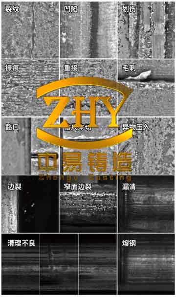
The illustration above shows common defects in sand casting, which our process aims to avoid. The simulated and actual production results confirm that the sand casting defect levels are well controlled.