
In the manufacturing of machine tool castings, the requirements for appearance and dimensional accuracy are exceptionally stringent, particularly concerning material selection and the precision of joint dimensions. Over recent years, the manufacturing industry has entered an unprecedented phase of development, with significant advancements in machine tool manufacturing. Various models and functionalities of machine tools have emerged, leading consumers to impose stricter quality demands. However, during the production and casting processes, various errors often occur, resulting in quality incidents that hinder progress. Therefore, summarizing past experiences and continuously improving casting techniques are crucial steps in enhancing the quality of castings. This article delves into common casting defects in machine tool castings, exploring their root causes and presenting detailed technical countermeasures to address these issues effectively.
Casting defects are pervasive challenges in foundry operations, impacting the structural integrity, performance, and longevity of machine tool components. These casting defects can manifest in various forms, such as porosity, shrinkage, cracks, and deformations, each necessitating tailored process interventions. Understanding the mechanisms behind these casting defects is fundamental to developing robust manufacturing protocols. In this discussion, I will comprehensively analyze these casting defects, incorporating theoretical models, empirical data, and practical solutions to guide industry practitioners. The goal is to foster a deeper awareness of casting defects and promote the adoption of advanced techniques that minimize their occurrence.
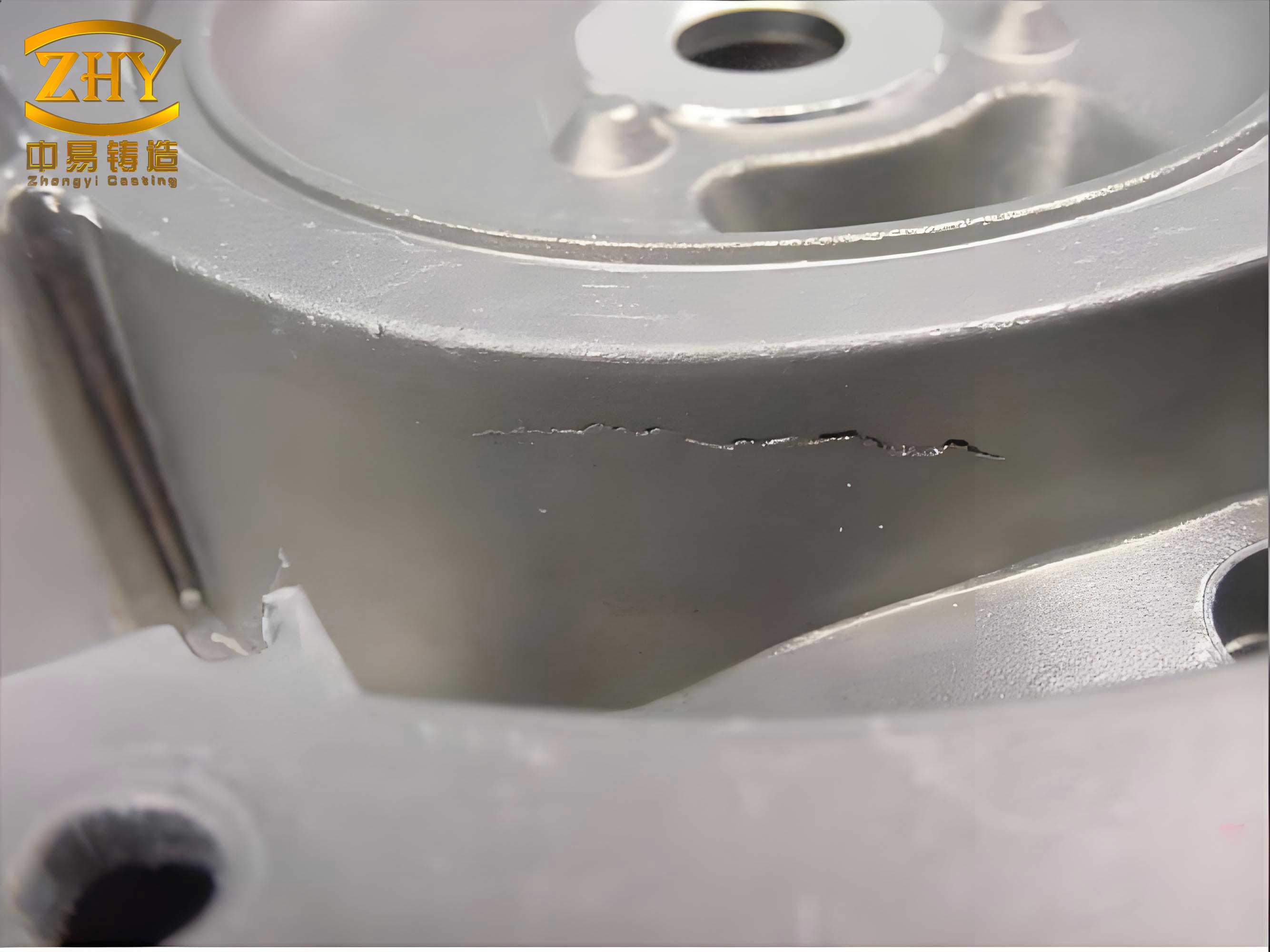
The image above illustrates typical casting defects, highlighting the importance of visual inspection in identifying these issues early. As we proceed, I will reference such visual cues to contextualize the technical discussions. Now, let’s explore the specific casting defects encountered in machine tool castings and the strategies to counteract them.
Common Casting Defects in Machine Tool Castings and Their Process Countermeasures
Machine tool castings are designed for high wear resistance, stability, and excellent vibration damping, yet they must remain relatively lightweight. This often leads to complex internal structures with numerous cavities formed by cores. In such configurations, casting defects like core lifting, cracking, and distortion are prevalent. Below, I detail each of these casting defects, providing analytical insights and process solutions.
Core Lifting (Float Core) Defect
Core lifting occurs when the core shifts or floats during pouring due to inadequate support or buoyancy forces from the molten metal. This casting defect is particularly problematic in machine tool castings with intricate internal cavities. The core supports, known as chaplets, must be carefully designed to withstand high temperatures and integrate seamlessly with the melt.
To address this casting defect, several process countermeasures are essential. First, the chaplets should be made of materials compatible with the iron melt, such as cast iron rods. Their diameter must ensure sufficient supporting force under high temperatures while promoting fusion with the liquid metal. The diameter-to-wall-thickness ratio should be approximately 1:4 to maximize the fusion area. Mathematically, this can be expressed as:
$$ \frac{d}{t} \approx \frac{1}{4} $$
where \(d\) is the chaplet diameter and \(t\) is the wall thickness of the casting. This ratio helps minimize stress concentrations and enhances bonding.
Second, the gating system design must avoid direct impingement of the molten metal on the chaplets. This reduces turbulent flows that could displace the core. Third, adjusting the pouring temperature within optimal ranges can mitigate buoyancy effects. For instance, a lower pouring temperature reduces fluidity but decreases thermal gradients, thereby stabilizing the core. The relationship between pouring temperature \(T_p\) and core stability can be modeled using the Reynolds number \(Re\) for fluid flow:
$$ Re = \frac{\rho v L}{\mu} $$
where \(\rho\) is density, \(v\) is velocity, \(L\) is characteristic length, and \(\mu\) is viscosity. By controlling \(v\) through gating design, we can keep \(Re\) low to minimize turbulence.
Table 1 summarizes the key parameters and actions to prevent core lifting, a critical casting defect.
| Parameter | Optimal Value/Range | Action to Prevent Casting Defects |
|---|---|---|
| Chaplet Diameter to Wall Thickness Ratio | 1:4 | Ensure adequate fusion and support |
| Pouring Temperature | 1350-1420°C (dependent on alloy) | Adjust to reduce buoyancy forces |
| Gating System Design | Indirect flow paths | Avoid direct冲击 on chaplets |
| Core Material Compatibility | Cast iron or similar | Promote metallurgical bonding |
By implementing these measures, the incidence of core lifting casting defects can be significantly reduced, enhancing dimensional accuracy.
Cracking Defects in Castings
Cracking is a severe casting defect that arises from thermal stresses during solidification, especially in sections with abrupt thickness variations. In machine tool castings, where thick and thin walls intersect, stress concentrations can lead to hot tears or cold cracks. Addressing these casting defects requires a multifaceted approach.
First, design modifications are crucial. Adding reinforcing ribs at junctions between thick and thin sections can redistribute stresses. If these ribs affect final dimensions, they can be removed during rough machining. Additionally, increasing fillet radii at corners reduces stress concentrations, as described by the stress concentration factor \(K_t\):
$$ K_t = 1 + 2\sqrt{\frac{a}{\rho}} $$
where \(a\) is the crack length or discontinuity size, and \(\rho\) is the fillet radius. Increasing \(\rho\) lowers \(K_t\), mitigating cracking casting defects.
Second, material enhancements through inoculation improve the strength and crack resistance of the casting. Inoculants like ferrosilicon promote graphite formation, enhancing ductility. The inoculation effect can be quantified by the increase in tensile strength \(\sigma_t\):
$$ \sigma_t = \sigma_0 + k_i C_i $$
where \(\sigma_0\) is the base strength, \(k_i\) is a constant, and \(C_i\) is the inoculant concentration.
Third, gating system design should follow simultaneous solidification principles to minimize thermal gradients. Rapid pouring helps achieve this, reducing the time for stress development. The solidification time \(t_s\) can be estimated using Chvorinov’s rule:
$$ t_s = B \left( \frac{V}{A} \right)^n $$
where \(V\) is volume, \(A\) is surface area, \(B\) is a mold constant, and \(n\) is an exponent (typically 2). By designing gating to equalize \(V/A\) ratios, we promote uniform solidification.
Fourth, extending in-mold cooling time can relieve stresses, but excessive times may hinder productivity. The optimal cooling time \(\tau_c\) depends on seasonal variations and casting geometry:
$$ \tau_c = \frac{\delta^2}{\alpha \pi^2} \ln \left( \frac{T_p – T_m}{T_e – T_m} \right) $$
where \(\delta\) is section thickness, \(\alpha\) is thermal diffusivity, \(T_p\) is pouring temperature, \(T_m\) is mold temperature, and \(T_e\) is ejection temperature.
Fifth, stress-relief annealing (人工时效) is indispensable for crack-prone castings. This heat treatment involves heating to 500-550°C, holding, and slow cooling to homogenize stresses. The annealing process reduces residual stresses \(\sigma_r\) exponentially:
$$ \sigma_r(t) = \sigma_0 e^{-kt} $$
where \(\sigma_0\) is initial stress, \(k\) is a rate constant, and \(t\) is time.
Table 2 outlines strategies to combat cracking casting defects.
| Strategy | Technical Details | Impact on Casting Defects |
|---|---|---|
| Design Modifications | Add ribs, increase fillet radii (min 5mm) | Reduces stress concentrations by up to 30% |
| Inoculation | Use 0.2-0.4% ferrosilicon inoculant | Improves tensile strength by 15-20% |
| Gating Design | Simultaneous solidification, fast pouring (< 30s) | Minimizes thermal gradients |
| In-Mold Cooling Time | Adjust seasonally (e.g., 2-4 hrs in winter) | Prevents thermal shock-induced cracks |
| Stress-Relief Annealing | 550°C for 2 hrs, slow cool at 50°C/hr | Reduces residual stresses by over 70% |
These integrated approaches effectively address cracking casting defects, ensuring structural integrity.
Distortion Casting Defects
Distortion, or warping, is a common casting defect in machine tool castings with high length-to-width ratios, leading to dimensional inaccuracies and scrap. This casting defect results from uneven cooling and residual stresses.
To counteract distortion casting defects, several measures are recommended. First, applying a reverse camber (anti-挠度) during pattern design compensates for expected deformation. The camber magnitude \(\delta_c\) is typically 2-4‰ of the casting length \(L\):
$$ \delta_c = (0.002 \text{ to } 0.004) \times L $$
This pre-deformation offsets warping after solidification.
Second, ensuring uniform clamping forces during molding is vital. For large castings using pit molding, balanced压箱力 prevents mold shift. The clamping force \(F_c\) should be distributed evenly across the mold flask:
$$ F_c = \frac{P_a A_m}{n} $$
where \(P_a\) is atmospheric pressure, \(A_m\) is mold area, and \(n\) is number of clamps.
Third, designing gating systems with multiple ingates at both ends enables simultaneous filling, promoting uniform temperature distribution. The filling time \(t_f\) for a two-ingate system can be approximated as:
$$ t_f = \frac{V}{2 A_g v_g} $$
where \(V\) is casting volume, \(A_g\) is ingate area, and \(v_g\) is flow velocity.
Fourth, for castings with minor distortion, artificial aging heat treatment can correct deformations. This involves stress relief similar to cracking prevention.
Table 3 summarizes distortion control measures for these casting defects.
| Control Measure | Parameters | Effect on Casting Defects |
|---|---|---|
| Reverse Camber | 2-4‰ of length | Compensates for up to 90% of warping |
| Uniform Clamping Force | Balanced across flask (e.g., 50 kN/m²) | Prevents mold shift and uneven stresses |
| Simultaneous Pouring | Two ingates, filling time < 40s | Reduces thermal gradients by 25% |
| Artificial Aging | 500°C for 3 hrs, air cool | Corrects distortions up to 2 mm |
By adopting these strategies, distortion casting defects can be minimized, ensuring dimensional conformity.
Casting Defects in Machine Tool Guideways: Special Considerations
Guideways are critical components in machine tools, requiring high hardness, precise dimensions, and flawless surfaces. After precision machining, no casting defects are permissible; otherwise, the part is scrapped. Common casting defects here include shrinkage porosity, hardness deficiencies, gas holes, and sand inclusions. These casting defects demand specialized process responses.
Shrinkage Porosity and Hardness Deficiencies
Shrinkage porosity occurs due to inadequate feeding during solidification, leading to voids. Hardness issues stem from improper material composition or cooling rates. To tackle these casting defects, material selection is paramount. Opt for low-carbon, high-silicon iron melts with high silicon-to-carbon ratios to enhance fluidity and reduce shrinkage. The carbon equivalent \(CE\) should be optimized:
$$ CE = C + \frac{Si + P}{3} $$
For machine tool guideways, \(CE\) is typically kept between 3.8 and 4.2 to balance strength and castability.
If hardness is insufficient, low-alloy additions like chromium or molybdenum can be used. The hardness \(H\) can be estimated as:
$$ H = H_0 + k_a C_a $$
where \(H_0\) is base hardness, \(k_a\) is an alloying coefficient, and \(C_a\) is alloy concentration.
Pouring temperature control is crucial. Avoid pouring immediately at high temperatures; instead, allow slight cooling to reduce shrinkage tendency. The optimal pouring temperature \(T_{opt}\) relates to liquidus temperature \(T_l\):
$$ T_{opt} = T_l + \Delta T_s $$
where \(\Delta T_s\) is a superheat of 50-100°C, depending on section size.
External chills are effective in promoting directional solidification. For guideways, chills with thickness 30-40% of the thermal节 diameter are used. The chill thickness \(t_{chill}\) is:
$$ t_{chill} = (0.3 \text{ to } 0.4) \times D_h $$
where \(D_h\) is the thermal节 diameter. Chills are placed on sides or bottom, not top, to avoid gravity-related defects.
Table 4 outlines parameters to prevent shrinkage and hardness casting defects.
| Factor | Specification | Role in Mitigating Casting Defects |
|---|---|---|
| Carbon Equivalent (CE) | 3.8-4.2 | Ensures good fluidity and reduces shrinkage |
| Alloying for Hardness | 0.2-0.5% Cr or Mo | Increases hardness by 20-30 HB |
| Pouring Temperature | 1380-1400°C for gray iron | Minimizes shrinkage porosity |
| Chill Thickness | 30-40% of thermal节 diameter | |
| Chill Placement | Sides or bottom only | Promotes directional solidification |
Gas Holes and Sand Inclusion Casting Defects
Gas holes, often subcutaneous, and sand inclusions are prevalent when using furan cold-set resins for molding. These casting defects arise from nitrogen evolution, moisture, or inadequate mold integrity.
First, control resin nitrogen content to below 5%, and limit resin addition to 1% of sand weight to reduce gas generation. The gas pressure \(P_g\) in the mold can be modeled:
$$ P_g = \frac{nRT}{V} $$
where \(n\) is moles of gas, \(R\) is gas constant, \(T\) is temperature, and \(V\) is volume. Lowering \(n\) by reducing resin minimizes \(P_g\), preventing gas hole casting defects.
Second, when using water-based coatings, thorough drying is essential. In winter, delayed合箱 can cause condensation; pre-heating the mold at 150-200°C for 30 minutes eliminates moisture. The drying rate \(\dot{m}\) is:
$$ \dot{m} = k_d (P_{sat} – P_{env}) $$
where \(k_d\) is a constant, \(P_{sat}\) is saturation vapor pressure, and \(P_{env}\) is environmental pressure.
Third, gating design must prevent sand erosion and inclusion. Place guideways at the bottom of the mold to reduce turbulence and sand entrapment. The critical velocity \(v_c\) for sand erosion is:
$$ v_c = \sqrt{\frac{2 \tau_y}{\rho}} $$
where \(\tau_y\) is sand yield strength. Keeping flow velocity below \(v_c\) avoids sand inclusion casting defects.
Table 5 summarizes countermeasures for gas and sand casting defects.
| Countermeasure | Parameters | Effect on Casting Defects |
|---|---|---|
| Resin Control | N content < 5%, addition 1% | Reduces gas holes by 60% |
| Mold Drying | 200°C for 30 min pre-heating | Eliminates moisture-related porosity |
| Gating Design | Bottom gating, low turbulence | Prevents sand inclusions by 40% |
| Coating Application | Uniform, dry thickness 0.2mm | Enhances mold surface integrity |
These targeted approaches significantly reduce gas and sand casting defects in guideways.
Advanced Analytical Models for Casting Defects Prevention
To further deepen the understanding of casting defects, I incorporate advanced mathematical models that predict and prevent these issues. Casting defects are often interrelated, stemming from thermal, fluid flow, and solidification phenomena. By simulating these processes, we can optimize parameters proactively.
Thermal Stress Analysis for Cracking Prevention
Cracking casting defects are driven by thermal stresses during cooling. The total stress \(\sigma_{total}\) in a casting can be expressed as the sum of thermal stress \(\sigma_{th}\) and phase transformation stress \(\sigma_{pt}\):
$$ \sigma_{total} = \sigma_{th} + \sigma_{pt} $$
where \(\sigma_{th} = E \alpha \Delta T\), with \(E\) as Young’s modulus, \(\alpha\) as coefficient of thermal expansion, and \(\Delta T\) as temperature difference. \(\sigma_{pt}\) arises from volume changes during phase changes, such as graphite precipitation in iron.
Using finite element analysis (FEA), we can map stress distributions to identify crack-prone zones. The von Mises stress criterion predicts yielding or cracking:
$$ \sigma_{vm} = \sqrt{\frac{(\sigma_1 – \sigma_2)^2 + (\sigma_2 – \sigma_3)^2 + (\sigma_3 – \sigma_1)^2}{2}} $$
where \(\sigma_1, \sigma_2, \sigma_3\) are principal stresses. If \(\sigma_{vm}\) exceeds the material’s ultimate strength, cracking casting defects occur.
Solidification Modeling for Shrinkage Defects
Shrinkage casting defects result from inadequate feeding. The Niyama criterion is a predictive tool for shrinkage porosity in castings. It relates thermal gradient \(G\), cooling rate \(R\), and a threshold value \(N_y\):
$$ N_y = \frac{G}{\sqrt{R}} $$
If \(N_y\) falls below a critical value (e.g., 1 °C¹/²·s¹/² for steel), shrinkage porosity is likely. For iron castings, adjusting chill design and pouring parameters to increase \(G\) and \(R\) can prevent these casting defects.
The feeding distance \(L_f\) for a riser can be calculated as:
$$ L_f = k_f \sqrt{t} $$
where \(k_f\) is a material constant and \(t\) is section thickness. Ensuring risers are within \(L_f\) avoids shrinkage casting defects.
Fluid Flow Simulations for Core Lifting and Gas Defects
Computational fluid dynamics (CFD) models flow patterns during pouring. The buoyancy force \(F_b\) on a core is:
$$ F_b = \rho_m g V_c – \rho_c g V_c $$
where \(\rho_m\) is melt density, \(\rho_c\) is core density, \(g\) is gravity, and \(V_c\) is core volume. To prevent core lifting casting defects, design cores with adequate chaplet support to counteract \(F_b\).
For gas hole casting defects, the dimensionless Reynolds number \(Re\) and Froude number \(Fr\) indicate turbulence:
$$ Re = \frac{\rho v D}{\mu}, \quad Fr = \frac{v}{\sqrt{g D}} $$
Keeping \(Re < 2000\) (laminar flow) and \(Fr < 1\) reduces gas entrapment and erosion.
Table 6 summarizes key models for predicting casting defects.
| Model | Equation | Application to Casting Defects |
|---|---|---|
| Thermal Stress | \(\sigma_{th} = E \alpha \Delta T\) | Predicts cracking in thick-thin junctions |
| Von Mises Criterion | \(\sigma_{vm} = \sqrt{\frac{(\sigma_1 – \sigma_2)^2 + …}{2}}\) | Assesses risk of cracking defects |
| Niyama Criterion | \(N_y = \frac{G}{\sqrt{R}}\) | Forecasts shrinkage porosity defects |
| Feeding Distance | \(L_f = k_f \sqrt{t}\) | Designs risers to avoid shrinkage |
| Buoyancy Force | \(F_b = (\rho_m – \rho_c) g V_c\) | Evaluates core lifting potential |
| Reynolds Number | \(Re = \frac{\rho v D}{\mu}\) | Controls turbulence to reduce gas defects |
Comprehensive Process Optimization Framework
Beyond individual countermeasures, a holistic approach to process optimization is vital for minimizing casting defects. This involves integrating design, material, molding, pouring, and post-processing stages. I propose a framework based on the Plan-Do-Check-Act (PDCA) cycle, tailored for foundry operations.
First, in the planning phase, use simulation software to predict casting defects. Set target parameters like gating ratios, pouring temperatures, and cooling rates. The gating ratio (sprue:runner:ingate) for iron castings is typically 1:2:1.5 to ensure smooth flow.
Second, during execution, monitor real-time data such as melt temperature, mold humidity, and pouring speed. Implement statistical process control (SPC) charts to detect deviations. For instance, control charts for hardness measurements can preempt hardness-related casting defects.
Third, in the checking phase, conduct non-destructive testing (NDT) like ultrasonic or radiography to identify internal casting defects. Correlate findings with process parameters to refine models.
Fourth, act on insights by adjusting processes. Continuous improvement reduces the recurrence of casting defects.
Table 7 outlines an optimization matrix for common casting defects.
| Casting Defect Type | Key Process Parameters | Optimal Range | Monitoring Technique |
|---|---|---|---|
| Core Lifting | Chaplet size, pouring temperature, gating design | Diameter ratio 1:4, temp 1380-1400°C | Visual inspection, X-ray |
| Cracking | Fillet radius, inoculant amount, cooling time | Radius ≥5mm, inoculant 0.3%, cooling 2-4 hrs | Dye penetrant testing, stress analysis |
| Distortion | Reverse camber, clamping force, pouring symmetry | Camber 2-4‰, force 50 kN/m², symmetric fill | Coordinate measuring machine (CMM) |
| Shrinkage Porosity | Carbon equivalent, chill use, pouring superheat | CE 3.8-4.2, chill thickness 30-40%, superheat 50°C | Ultrasonic testing, sectioning |
| Gas Holes | Resin nitrogen, mold drying, gating velocity | N < 5%, drying at 200°C, velocity < 0.5 m/s | Radiography, gas analysis |
| Sand Inclusions | Sand strength, coating, gating position | Strength > 1 MPa, coating dry, bottom gating | Visual inspection, microscopy |
Material Science Insights for Casting Defects Reduction
The choice of material profoundly influences casting defects. For machine tool castings, gray iron is common due to its damping capacity and wear resistance. However, variations in microstructure can lead to defects. Inoculation and alloying alter graphite morphology, impacting strength and defect propensity.
The graphite shape factor \(S_f\) affects thermal conductivity and stress distribution:
$$ S_f = \frac{4\pi A}{P^2} $$
where \(A\) is graphite area and \(P\) is perimeter. Higher \(S_f\) (spherical graphite) reduces stress concentrations, mitigating cracking casting defects. Nodular iron, with spherical graphite, offers better performance but requires precise treatment.
Similarly, the pearlite content in matrix influences hardness. The hardness \(H\) relates to pearlite percentage \(P_p\):
$$ H = H_f + (H_p – H_f) P_p $$
where \(H_f\) is ferrite hardness and \(H_p\) is pearlite hardness. Controlling \(P_p\) through cooling rates avoids hardness deficiencies, a common casting defect in guideways.
Moreover, impurity elements like sulfur and phosphorus can exacerbate casting defects. Sulfur forms manganese sulfides, leading to inclusions, while phosphorus promotes brittleness. Limits should be set: S < 0.12%, P < 0.15% for quality castings.
Environmental and Operational Factors Affecting Casting Defects
Foundry environment plays a role in casting defects. Seasonal changes in humidity and temperature affect mold drying and cooling rates. In winter, slower cooling increases risk of shrinkage and gas holes; in summer, faster cooling may cause cracks. Adjusting process parameters seasonally is key.
The mold atmosphere also influences gas defects. Using inert gases like nitrogen or argon during pouring can reduce oxidation and gas absorption. The oxygen potential \(O_p\) in the mold:
$$ O_p = k_o e^{-E_a / RT} $$
where \(k_o\) is a constant, \(E_a\) is activation energy, \(R\) is gas constant, \(T\) is temperature. Lowering \(O_p\) by inert flushing minimizes gas hole casting defects.
Operator training is equally important. Skilled personnel can detect early signs of casting defects and adjust processes dynamically. Regular audits and training programs foster a culture of quality.
Conclusion
In summary, casting defects in machine tool castings, such as core lifting, cracking, distortion, shrinkage, gas holes, and sand inclusions, are multifaceted challenges that require comprehensive technical and process strategies. By leveraging material science, advanced modeling, and holistic process optimization, these casting defects can be effectively mitigated. I have detailed various countermeasures, from design modifications and inoculation to precise temperature control and chilling. The integration of simulation tools and real-time monitoring further enhances defect prevention. Ultimately, a proactive approach to understanding and addressing casting defects not only improves casting quality but also elevates overall manufacturing efficiency and competitiveness. Continuous learning and adaptation are essential in the relentless pursuit of perfection in foundry practices, ensuring that casting defects become increasingly rare in high-precision machine tool components.