
Throughout my career in investment casting, I have consistently confronted the challenge of shrinkage porosity and cavities. The inherent constraints of our process—the need for effective gating and risering while managing shell preparation, dewaxing, and practical handling—often create isolated hotspots in casting parts that defy conventional feeding. Successfully producing sound casting parts hinges on a toolbox of strategies that go beyond standard textbook principles. Here, I will share a collection of practical measures and nuanced techniques developed from extensive experience to eliminate these frustrating defects.
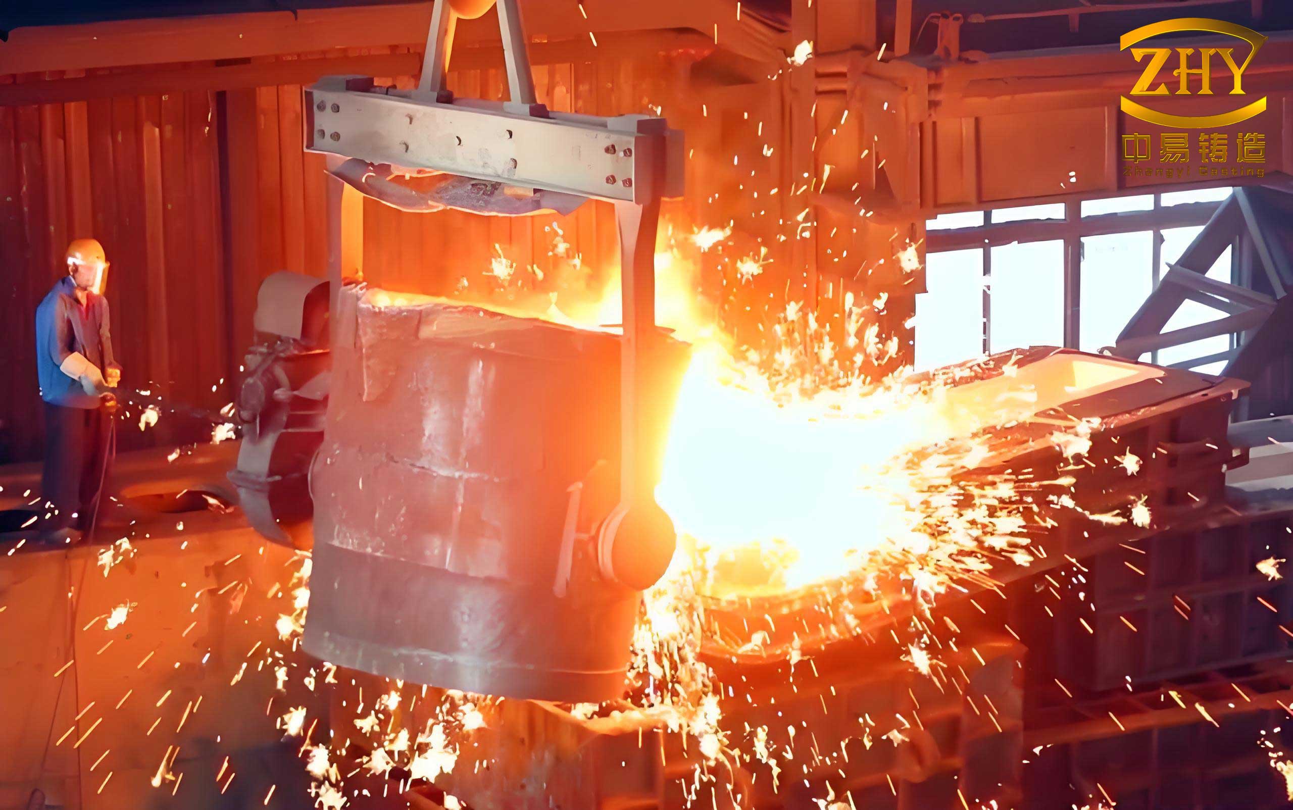
The battle against shrinkage begins with a fundamental understanding of solidification. Shrinkage occurs because metals are less dense as a liquid than as a solid. As a casting parts cools and freezes, it contracts. If liquid metal cannot flow into this contracting volume to compensate, a void—either a concentrated cavity (shrinkage cavity) or a diffuse spongy zone (porosity)—forms. The key to prevention is ensuring a continuous supply of liquid metal from a reservoir (a riser or the main gate) to the solidifying region until that region has completely solidified. This principle of directional solidification, where the farthest point from the feeder solidifies first and the feeder last, is our guiding light, but the path to achieving it in complex, thin-walled casting parts is often indirect.
1. Proactive Design: Reducing and Redistributing Thermal Mass
The most effective solution is often implemented before the first wax pattern is even made. By intelligently modifying the geometry of the casting parts, we can minimize the severity of hotspots from the outset.
1.1 Strategic Use of Cored Holes
Not every hole in a finished part needs to be machined; casting it can be a powerful tool. If a hole is located within a massive section, casting it removes material from the thermal center, effectively breaking up the hotspot. Conversely, if a hole creates a thin, isolated core of sand that becomes a severe hotspot itself, it is better to leave it as solid metal and machine it later. The decision is governed by the local geometry’s modulus (Volume/Surface Area ratio).
The modulus, $M$, is a critical parameter:
$$ M = \frac{V}{A} $$
where $V$ is the volume of the section and $A$ is its surface area. A higher modulus indicates a slower cooling rate. A design change is beneficial if it significantly reduces the modulus of the suspected hotspot.
| Situation | Action | Principle & Rationale |
|---|---|---|
| Hole located *within* a thick section. | Cast the hole. | Reduces volume $V$ of the hotspot, decreasing its modulus $M$ and promoting faster solidification relative to the feeding path. |
| Hole creates an *isolated* thin-walled core (e.g., a blind hole). | Do not cast; machine later. | Prevents creating an unsupported ceramic core with a very high surface area $A$, which draws heat rapidly from the surrounding metal, creating a localized shrinkage zone at the metal-core interface. |
1.2 Introducing Process Windows and Holes
When a functional feature creates an unavoidable hotspot, and post-casting machining is not feasible, we can add non-functional “process” features. A deep, blind cavity filled with shell material acts as an excellent insulator, creating a severe artificial hotspot. By opening a “window” in the side or end wall of this cavity, we expose the internal metal surface to the cooler shell, drastically increasing the effective surface area $A$ for heat transfer. The revised modulus becomes:
$$ M_{revised} = \frac{V}{A + A_{window}} $$
where $A_{window}$ is the area of the new opening. This increase in denominator causes faster solidification, often eliminating the shrinkage defect.
1.3 Optimizing Structural Geometry
Sharp corners, abrupt changes in section, and intersecting ribs are prime locations for hotspots. As a rule of thumb, I always advocate for:
- Generous Internal Radii: A sharp corner has a theoretically infinite local modulus. Adding a radius $r$ reduces the local thermal concentration. The effect is nonlinear; even a small radius provides a disproportionate benefit. For example, the thermal concentration factor for a corner can be approximated relative to a plate of thickness $T$ as a function of $r/T$.
- Gradual Transitions: Changing section thickness from $T_1$ to $T_2$ should be done over a transition length $L \geq 3 \times |T_1 – T_2|$. This smoothens the temperature gradient and prevents a localized hotspot at the step.
- Balanced Intersections: In T-junctions, the rib thickness should be 0.6 to 0.8 times the wall thickness to balance cooling rates. Avoid cruciform (cross) intersections at all costs; they create a central mass that is nearly impossible to feed. Staggering the ribs to create two T-junctions is always superior.
| Problem Feature | Recommended Modification | Key Parameter/Goal |
|---|---|---|
| Sharp Internal Corner | Add fillet radius $r$. | $r \geq 0.3 \times$ section thickness $T$. |
| Abrupt Section Change | Use tapered transition. | Transition length $L \geq 3 \times |T_1 – T_2|$. |
| T-Junction | Balance rib and wall thickness. | Rib thickness $t_{rib} \approx (0.6-0.8) \times t_{wall}$. |
| Cruciform Junction | Stagger ribs to form T-junctions. | Eliminate the central, unfed thermal mass. |
2. Enhancing Feedability: Creating and Sustaining Paths for Liquid Metal
When the design of the casting parts is fixed, we must manipulate the process to ensure liquid metal can reach and compensate for shrinkage.
2.1 Designing Artificial Feeding Channels (Process Bars)
A common dilemma is an isolated hotspot separated from the main gate by a thin, solidifying section that acts as a barrier. The solution is to add a sacrificial “process bar” or “feeding channel.” This bar is designed with a modulus greater than that of the hotspot it is intended to feed, ensuring it remains liquid longer. Its design is critical:
$$ M_{channel} > M_{hotspot} $$
Typically, I aim for $M_{channel} \approx 1.2 \times M_{hotspot}$. This channel provides a direct hydraulic and thermal path from the feeder to the problematic area. After heat treatment, it is removed by grinding or cutting. This technique is invaluable for saving otherwise scrap casting parts.
2.2 Clustered Molding for Thermal Management
For very thin-walled casting parts with small, dispersed hotspots, conventional gating can lead to premature freezing. In these cases, I use a “clustered” or “dense” tree assembly. Multiple wax patterns are arranged with their thin walls in close proximity. During shell building, the slurry bridges the gaps, effectively creating a single, thick-walled ceramic mass around the cluster. This provides superior thermal insulation. During pouring, the closely spaced castings mutually radiate heat, slowing the cooling of the entire group and maintaining fluidity in the feeding paths long enough for the small hotspots to be fed. This method can be analyzed by considering the effective modulus of the cluster versus an isolated part.
2.3 Strategic Application of External Insulation
Sometimes, the feeding channel itself is at risk of freezing too quickly. Post-dewaxing, before preheating and pouring, we can apply ceramic fiber blanket or other insulating materials to specific external regions of the shell. By wrapping insulation around the shell covering a long, thin feed path, we drastically reduce the heat loss rate from that channel. The heat flux $q$ through the shell with insulation is reduced:
$$ q_{insulated} = \frac{T_{melt} – T_{ambient}}{R_{shell} + R_{insulation}} $$
where $R$ denotes thermal resistance. Increasing $R_{insulation}$ lowers $q$, preserving liquid metal in the channel to feed distal hotspots in the casting parts.
| Technique | Application Scenario | Governing Principle / Design Rule |
|---|---|---|
| Process Bar / Channel | Isolated hotspot with restricted feed path. | $M_{channel} > M_{hotspot}$ (aim for ~1.2x). Provides direct liquid path. |
| Clustered Assembly | Very thin-walled parts with small hotspots. | Increases effective thermal mass and insulation. Slows cooling of the entire group. |
| External Shell Insulation | Long, vulnerable feeding channels. | Increases thermal resistance $R$ to reduce heat flux $q$, delaying solidification of the channel. |
3. Mastering Solidification: Controlling the Temperature Field
The ultimate goal is to control the order in which sections of the casting parts solidify. We typically strive for directional solidification, but sometimes simultaneous solidification is the answer.
3.1 Forcing Directional Solidification
When a single dominant hotspot exists, we can use aggressive cooling to make it solidify first, establishing a clear temperature gradient toward the feeder.
- Bottom Water Quenching: For trees assembled on a flat plate (horizontal gating), the lowest point in the mold is the farthest from the pour cup. If we place the critical hotspot there, we can, immediately after pouring, lower the bottom of the assembly into a water bath. This applies a massive heat extraction rate, described by a very high heat transfer coefficient $h_{water}$. The solidification time $t_s$ for the quenched section is dramatically reduced:
$$ t_s \propto \frac{1}{h} $$
This forces that section to freeze early, allowing metal from above to feed it effectively. - Targeted Air or Water Cooling: For internal cavities or specific external bosses, we can use directed air jets or water sprays post-pouring. This requires careful planning of the tree orientation on the cooling conveyor or rack.
- Internal Chills: This is a highly effective but often overlooked technique in investment casting. A pre-formed piece of metal of the same or similar alloy is embedded in the wax pattern at the hotspot location. During shell building and dewaxing, it remains in place. During pouring, the chill rapidly extracts heat from the surrounding metal because it has high thermal conductivity and significant mass, acting as a heat sink. The chill’s effectiveness is related to its modulus and the contact area. It is ideal for thick sections in otherwise thin-walled casting parts.
3.2 Promoting Simultaneous Solidification
For large, planar casting parts with numerous, dispersed hotspots of similar modulus, directional feeding from a single point is impossible. The strategy flips: instead of creating a gradient, we try to equalize the temperature field so all sections solidify at nearly the same time, minimizing the need for long-range liquid feeding. This is achieved by gating into a thin, central area of the part. The large thermal mass of the gate and runner system acts as a “heater,” keeping the central region molten for an extended period. This heat radiates to and slows the cooling of the peripheral hotspots, while the thin central section itself can freeze quickly without causing shrinkage. The goal is to balance the solidification times $t_{s,i}$ of the $N$ major sections:
$$ \text{Minimize } \sigma_t = \sqrt{\frac{1}{N}\sum_{i=1}^{N}(t_{s,i} – \bar{t_s})^2} $$
where $\sigma_t$ is the standard deviation of solidification times and $\bar{t_s}$ is the mean solidification time. Gating into a thin section helps reduce $\sigma_t$ for parts with multiple similar-mass hotspots.
| Strategy | Objective | Key Mechanism / Action | Typical Application |
|---|---|---|---|
| Directional Solidification | Create a thermal gradient from hotspot to feeder. | Aggressive, localized cooling (water quench, air blast, internal chill). | Parts with one or two dominant, severe hotspots. |
| Simultaneous Solidification | Equalize cooling rates across multiple sections. | Gate into thin areas; use gates/runners as thermal buffers. | Large, thin parts with many similar, dispersed hotspots. |
4. The Integrated Approach: Analysis and Decision-Making
Solving shrinkage in complex casting parts is rarely about applying a single trick. It is an iterative analytical process. My approach typically follows this sequence:
- Identify the Hotspot(s): Use modulus calculations and experience to locate potential problem areas on the drawing of the casting parts.
$$ M_{candidate} = \frac{V_{section}}{A_{cooling}} $$
Compare moduli of adjoining sections. The area with the highest $M$ is the most likely suspect. - Evaluate Design for Manufacturing (DFM) Potential: Can the part be slightly modified with a radius, a taper, or a process hole? This is always the most cost-effective long-term solution.
- Plan the Feeding Strategy: Can a natural feeder be placed? If not, is a process bar viable? Calculate required $M_{channel}$.
- Choose a Solidification Strategy: Based on the number and location of hotspots, decide on directional or simultaneous solidification. This dictates gating location.
- Select Auxiliary Techniques: Determine if chills, cluster assembly, or post-pour cooling will be necessary. Model the tree assembly to enable these actions (e.g., orienting the part for bottom quenching).
Every decision is a balance between casting yield, shell-making complexity, finishing cost, and ultimate reliability of the casting parts.
5. Conclusion and Future Perspectives
The prevention of shrinkage in investment casting parts is a multifaceted challenge that blends fundamental metallurgical principles with pragmatic shop-floor ingenuity. There is no universal formula, but a deep understanding of heat transfer and solidification, combined with the strategies outlined—from proactive geometry changes and artificial feed channels to aggressive cooling techniques and strategic temperature field management—provides a robust framework for success. The core philosophy is to always think thermally: manipulate volumes, surfaces, and heat extraction rates to ensure every volume element of the casting parts has access to liquid metal until the moment it solidifies. As simulation software becomes more accessible and accurate, these experiential techniques can be validated and optimized digitally before any metal is poured, leading to faster development of robust processes for even the most challenging casting parts. The journey from a defective casting to a sound one is a systematic application of physics, guided by experience and creativity.