
Abstract: Block casting, due to its complex shape, has traditionally been produced using sand casting processes. However, defects often occur at the bottom of the casting blanks, primarily due to limitations in the design of the gating system. The introduction and application of 3D printing technology have addressed these limitations, enabling the simulation of the pouring process and potential defect locations through software, thereby improving the yield of castings. This paper discusses the application of 3D printing technology in block casting, focusing on its advantages, technical principles, and practical cases.
Keywords: block casting; sand casting; 3D printing technology
1. Introduction
3D printing, an emerging technology in recent years, has seen increasing applications across various industries, including the casting industry. This technology has been widely used in sand casting and investment casting for new product development, small-batch production, and personalized customization. It offers digitalization, flexibility, precision, and environmental friendliness. This paper explores the application of 3D printing technology in block casting, particularly focusing on the three-dimensional binder jetting printing technology.
2. Overview of 3D Printing
In the field of sand casting, two primary 3D printing technologies are widely used: three-dimensional binder jetting printing and selective laser sintering. The casting process typically involves three-dimensional modeling, importing the model, 3D printing the sand mold and core, mold assembly and pouring, and finally obtaining the casting. This paper mainly introduces the three-dimensional binder jetting printing technology.
3. Three-Dimensional Binder Jetting Printing Technology
3.1 Process Principle
The computer slices the prepared three-dimensional CAD model of the sand mold (core) into horizontal layers of a certain thickness, converting it into a collection of two-dimensional layer information recognizable by the printer. The printer’s computer then directs the nozzles to jet binder onto the surface of the prepared sand mixed with a curing agent. The layers are bonded together through the binder, and the process repeats until the sand mold (core) is completed.
3.2 Forming Equipment
A 3D printer mainly consists of a jetting system, sand supply system, motion control system, and computer software and hardware.
3.3 Forming Materials
The materials used include base sand, curing agent, binder, and auxiliary materials.
3.4 Process Level
The dimensional accuracy of the printed sand mold (core) generally ranges from DCTG10 to DCTG12, with a surface roughness of Ra ≤ 25µm. The tensile strength at room temperature is 1.0–2.0 MPa, the flexural strength is 2.8–4.5 MPa, and the gas evolution at 1000°C is 6–20 mL/g, meeting the requirements of most casting sand molds (cores).
4. Application Case: Shell Casting
4.1 Traditional Process and Limitations
The shell, a critical component of a faucet, supports the installation of various faucet accessories. Due to its irregular geometry and internal connecting ribs and shaped holes, it is difficult to machine after casting. Therefore, the actual manufacturing process combines casting and machining.
The traditional casting process involves mixing sand, molding and core-making, steelmaking and pouring, mold stripping and cleaning, and inspection. For small-batch production of shells, manual molding is used with acid-curing furan resin self-hardening sand. The gating system is designed as a bottom-pouring type to ensure smooth metal filling, reduce impact on the sand mold and core, minimize metal oxidation, and facilitate gas venting. The upper part of the mold accommodates the risers, which compensate for shrinkage during casting to prevent shrinkage cavities and porosity, while also serving as gas vents, slag collectors, and guides for metal filling.
However, cracks were found at the bottom of the shell during processing, with irregular, discontinuous, and scattered crack sizes ranging from 2 to 3 mm. Some cracks are not visible to the naked eye and require magnetic particle inspection to confirm their locations. Analysis revealed that the defects were closely related to the design of the gating system. The main causes of casting defects include:
- Limited internal gates, hindering uniform metal filling.
- High temperature at the lower part of the casting, unfavorable for shrinkage compensation and excessive metal consumption.
- Small riser size, inadequate for shrinkage compensation.
Modifying the mold or gating system is challenging due to the complexity of the sand mold and the long trial production cycle. Therefore, the defect issue in shells persisted and remained unresolved for a long time.
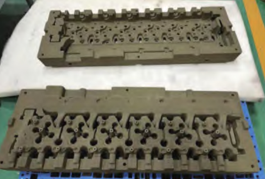
4.2 Implementation of the Shell 3D Printing Solution
The shell has a maximum contour size of 628 mm × 483 mm × 432 mm, a basic wall thickness of 26.5 mm, and technical requirements for a casting dimensional accuracy of DCTG10 and a surface roughness of Ra ≤ 25µm. The sand mold is assembled, consisting of upper and lower molds, body mold, and intermediate cores.
The 3D printing process involves mold parting analysis, casting process design, casting pouring simulation, casting process optimization modeling, 3D printing, sand mold cleaning, coating application, core assembly, mold filling and compaction, pouring, mold stripping and cleaning, and inspection. The shell casting weighs 265 kg, with a poured steel weight of 350 kg and a pouring time of 20–25 seconds. An open, bottom-pouring gating system is used, with a cross-sectional ratio of ΣA直: ΣA横: ΣA内 = 1:1.3:1.8. The gating system is formed by leaving voids during sand mold printing.
The surface floating sand thickness of the 3D-printed sand mold is approximately 0.4 mm, and the coating layer thickness is about 0.3 mm. Relevant sand cores are surface-infiltrated and dried in a drying oven along with other sand cores for 70 minutes before manual core assembly and fastening with screws.
The shell gating system is optimized during 3D printing:
- Enlarging the riser size to increase shrinkage compensation.
- Increasing the number of internal gates and distributing them to facilitate solidification and shrinkage compensation of the casting.
Additionally, subsidies are set at thick positions of the casting, and the metal filling, mold filling, and solidification processes are simulated. The simulation results show a smooth metal filling process and orderly solidification. After several iterations of process optimization, the 3D-printed shell castings fully meet the technical requirements, with significant improvements in overall performance and appearance quality.
Table 1: Comparison of Traditional and 3D Printing-Based Casting Processes
| Process Aspect | Traditional Sand Casting | 3D Printing-Based Sand Casting |
|---|---|---|
| Gating System Design | Limited flexibility | High flexibility and precision |
| Defect Rate | High | Low |
| Production Cycle | Long | Short |
| Cost | Lower (for large-batch production) | Higher (for small-batch production) |
| Customization | Limited | High |
5. Conclusion
- The primary cause of shell defects lies in the gating system. By improving the gating system and leveraging 3D printing technology, the issue of shell defects has been resolved.
- Through continuous optimization of the 3D printing technology solution, the overall process yield of shells has increased by 6%–8%.
- Although the manufacturing cost of 3D printing is higher than traditional casting, its shorter production cycle makes it suitable for small-batch production.
- Materials are a crucial foundation for the development of 3D printing technology and a significant factor determining its broader application.