
For decades, the dimensional verification of large steel castings has been a cornerstone of quality assurance in heavy industry. My extensive experience in this field has been defined by a constant battle against the limitations of traditional measurement tools. The landscape is changing, however, driven by the relentless push for more complex geometries, tighter tolerances, and faster production cycles. This narrative details the pivotal transition from manual, labor-intensive methods to the adoption of sophisticated optical space measurement systems, a journey that has fundamentally reshaped our approach to ensuring the dimensional integrity of every steel casting that leaves our facility.
The traditional arsenal consisted primarily of manual tools—calipers, tapes, and height gauges—and large, fixed three-dimensional scribing machines. While these methods served a purpose, their shortcomings became increasingly apparent. The scribing machines, though offering some level of coordinate measurement, were monolithic. They required the steel casting to be transported to a dedicated, vibration-isolated platform—a costly and time-consuming logistical feat for components often weighing tens of tons. Their measurement volume was physically constrained by the machine’s gantry, and their probing arms could not reach into deep cavities, undercuts, or the intricate internal passages common in modern turbine or pump casings. The measurement accuracy, often no better than ±0.5 mm, was a composite of machine error, thermal drift, and, most significantly, human error in reading scales, interpreting 2D drawings, and performing manual calculations for complex surfaces.
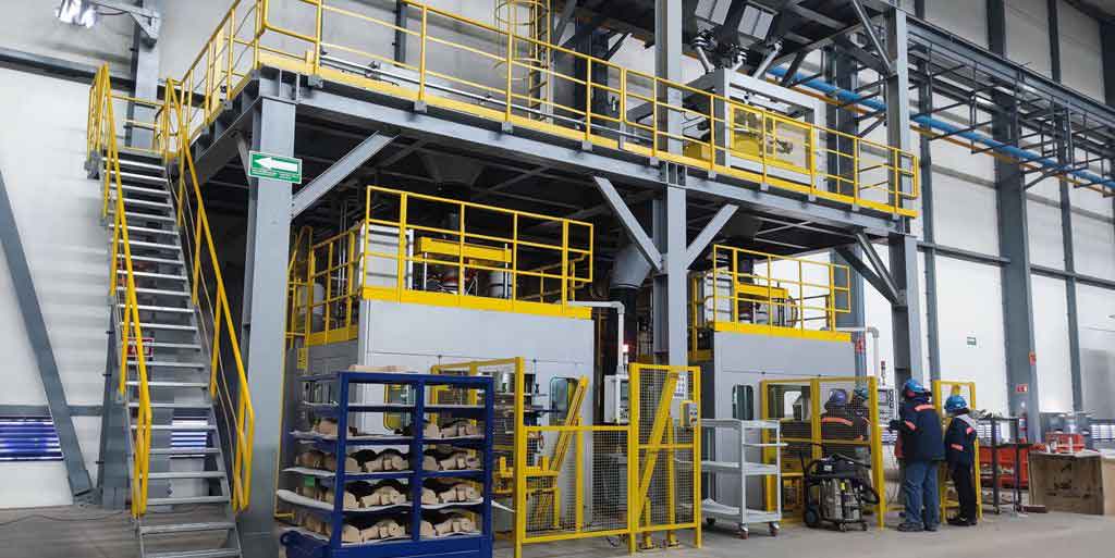
The production environment for a large steel casting is not a cleanroom; it is a dynamic space with temperature gradients, dust, and inherent vibrations. Fixed machines struggled in these conditions. Furthermore, the entire pre-casting process—measuring core boxes, verifying sand cores in deep pits, or checking mold assembly (coping and drag) before pouring—was essentially a dimensional black box. We had no reliable, quantitative data until the first rough casting was produced, often leading to costly and time-consuming repairs. This gap in process control was unacceptable. The need for a portable, high-precision, and digitally integrated solution was not just an improvement; it was an imperative for the future of manufacturing high-integrity steel castings.
The breakthrough came with the implementation of two complementary optical technologies: Industrial Photogrammetry and articulated arm-based or camera-tracked contact systems, often referred to as “light pen” measurement. These systems did not merely replace old tools; they introduced a new paradigm of “digital thread” connectivity from the CAD model to the finished part.
The Photogrammetry Revolution: Capturing Reality in Millions of Pixels
Industrial photogrammetry is a non-contact, optical 3D coordinate measurement technique. At its core, it solves a fundamental geometric problem: determining the 3D coordinates of points on an object by analyzing photographs taken from different angles. For a steel casting, the process begins with the application of small, circular retro-reflective targets onto the surface of the component. These targets become high-contrast reference points in the images.
A high-resolution, calibrated metric camera is then used to capture dozens, sometimes hundreds, of overlapping images of the steel casting from all conceivable vantage points. The principle is based on triangulation. Each target point is imaged in at least two, but preferably more, photographs. By knowing the precise interior orientation of the camera (focal length, principal point, lens distortion parameters) and the relative exterior orientation (position and angle) of each camera station, the 3D coordinates of each target can be calculated through a bundle adjustment process.
The mathematical foundation is robust. For a point $P$ with world coordinates $(X, Y, Z)$, its projection onto an image taken from camera position $i$ is given by the collinearity equations:
$$ x_{ij} – x_p = -c \frac{r_{11}(X_j – X_{0i}) + r_{12}(Y_j – Y_{0i}) + r_{13}(Z_j – Z_{0i})}{r_{31}(X_j – X_{0i}) + r_{32}(Y_j – Y_{0i}) + r_{33}(Z_j – Z_{0i})} + \Delta x $$
$$ y_{ij} – y_p = -c \frac{r_{21}(X_j – X_{0i}) + r_{22}(Y_j – Y_{0i}) + r_{23}(Z_j – Z_{0i})}{r_{31}(X_j – X_{0i}) + r_{32}(Y_j – Y_{0i}) + r_{33}(Z_j – Z_{0i})} + \Delta y $$
Where:
- $(x_{ij}, y_{ij})$ are the image coordinates of point $j$ in photo $i$.
- $(x_p, y_p)$ are the coordinates of the principal point.
- $c$ is the calibrated focal length.
- $r_{11}…r_{33}$ are the elements of the rotation matrix defining the camera’s angular orientation.
- $(X_{0i}, Y_{0i}, Z_{0i})$ are the coordinates of the camera’s perspective center for photo $i$.
- $(X_j, Y_j, Z_j)$ are the unknown world coordinates of point $j$.
- $(\Delta x, \Delta y)$ are lens distortion corrections.
A simultaneous least-squares bundle adjustment solves for all unknown parameters—the 3D coordinates of all target points and the exterior orientation of all camera stations—minimizing the discrepancies between measured and projected image coordinates. The result is a dense, accurate point cloud representing the measured steel casting. This point cloud is then aligned (best-fit) to the nominal CAD model in the analysis software, and a comprehensive deviation color map is generated. The system’s accuracy is remarkable, typically following a formula like:
$$ \text{Measurement Uncertainty} = A + B \cdot L $$
Where $A$ is a constant term (e.g., 10-20 µm) and $B$ is a scale factor (e.g., 10-20 µm/m), and $L$ is the size of the measured object. For a 5-meter steel casting, this translates to an uncertainty on the order of ±0.1 mm, a five-fold improvement over traditional methods.
Light Pen Measurement: Digital Touch for Critical Features
While photogrammetry excels at capturing global form and thousands of discrete points, certain tasks require physical probing. This is where the second pillar of our new strategy comes in: the portable coordinate measuring system with a handheld “light pen” or probe. This system typically uses one or more optical sensors (cameras) that track the position of infrared LEDs or spherical reflectors mounted on a rigid probe. As the operator touches the stylus tip to specific features on the steel casting—a machined datum, a hole center, a sharp edge—the system dynamically calculates the tip’s 3D coordinates in real-time.
The principle is again triangulation, but in real-time. The sensors continuously image the LEDs on the probe. Knowing the fixed geometric relationship between the LED constellation and the stylus tip (established during calibration), the system can compute the tip’s position as it moves. The probe can be used to:
- Precisely establish and mark machining datums on a rough steel casting.
- Measure geometric features like circles, cylinders, and planes directly.
- Perform detailed inspections in localized areas where photogrammetry targets may not be practical.
Its key advantage in the noisy environment of a steel foundry is its inherent robustness to vibration. Because it takes instantaneous measurements at the moment of contact, short-duration vibrations do not integrate into error as they would with a slow, scanning CMM arm.
A Synergistic Workflow: From Digital Model to Verified Steel Casting
The true power is unlocked by integrating these systems into a seamless workflow. The following table summarizes the comparative advantages:
| Aspect | Traditional 3D Scribing | Industrial Photogrammetry | Light Pen System |
|---|---|---|---|
| Portability | Fixed, immobile | Fully portable (camera only) | Portable (sensor unit + probe) |
| Measurement Volume | Limited by machine envelope | Virtually unlimited, scalable | Large (several meters radius) |
| Typical Accuracy | ~ ±0.5 mm | ± (0.01 + 0.01*L) mm | ~ ±0.03 – 0.05 mm |
| Data Type | Sparse points, manual logging | Dense point cloud, full-field deviation | Discrete features, geometric elements |
| Key Application | Final part inspection (if movable) | Global form analysis, process control at all stages | Datum establishment, localized feature inspection |
| Impact on Logistics | High (requires part transport) | None (measure in situ) | Low (setup required) |
Our implemented process flow is now digital and comprehensive:
- Digital Foundation: Every steel casting project starts with a validated 3D CAD model, which serves as the absolute nominal reference throughout the product lifecycle.
- In-Process Control: We now measure throughout manufacturing. Using photogrammetry, we verify sand core dimensions in the core boxes, check the assembly of large molds in the casting pit before metal is poured, and assess core positioning. This prevents errors from propagating to the final steel casting.
- Post-Casting Analysis: After shakeout and heat treatment, the rough steel casting is measured in its storage area. Retro-reflective targets are applied, and a photogrammetric scan is performed. Within hours, we have a full deviation report showing shrinkage, warpage, or core shift, allowing us to plan machining allowances or necessary weld repairs with precise data.
- Datum Establishment: For the first machining setup, we use the light pen system. The probe is used to physically touch off on datum features identified from the photogrammetry analysis (or on as-cast features). This allows us to accurately translate the digital coordinate system from the CAD model onto the physical steel casting and mark it for the machinist, ensuring the first cut is correct.
- Final Verification: After machining, a final combined check can be performed. Photogrammetry verifies overall dimensions and surface profiles, while the light pen precisely measures critical machined bores, seal grooves, and flange flatness.
Quantifiable Results and Future Vision
The impact of adopting optical space measurement for steel castings has been transformative, yielding measurable outcomes across key performance indicators:
$$ \text{Efficiency Gain} = \frac{T_{traditional} – T_{optical}}{T_{traditional}} \approx 60-70\% $$
$$ \text{Cost Avoidance} = C_{transport} + C_{rework\_due\_to\_error} + C_{model\_making} $$
The variables in the cost equation have been drastically reduced. Elimination of unnecessary crane moves for measurement alone has saved substantial time and risk. Early error detection has cut scrap and heavy rework. In some cases, for simple or symmetrical steel castings, we have moved towards “virtual modeling,” where the mold is built directly from the digital data without a physical pattern, saving weeks and significant cost.
Furthermore, the data collected creates a valuable feedback loop. Statistical analysis of deformation patterns across multiple similar steel castings allows us to predict and pre-compensate patterns in the CAD stage, steadily improving first-time yield. The ability to digitize the entire as-built geometry of a steel casting also provides invaluable data for reverse engineering, legacy part reproduction, and finite element analysis validation.
In conclusion, the journey from manual measurement to optical metrology represents more than a simple tool change. It is a fundamental shift towards a data-driven, closed-loop manufacturing process for large steel castings. The integration of photogrammetry and portable CMM technology has broken down the barriers of size, location, and complexity. It has given us eyes and a precise digital touch throughout the entire journey of a steel casting, from a pile of sand to a finished, high-precision component. This is no longer just inspection; it is intelligent, pervasive quality assurance that builds confidence, drives efficiency, and unlocks new possibilities in the design and manufacture of the massive, complex steel castings that modern industry depends on.