
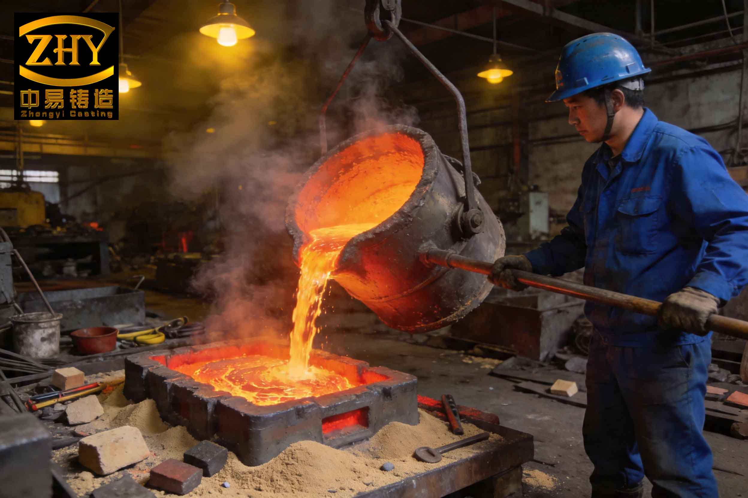
In industrial foundry practice, the persistent and patterned recurrence of casting defects presents a significant challenge to productivity, cost control, and quality assurance. One such formidable issue, observed during the continuous casting of steel wheels using a bottom-pour ladle system, is the formation of slag inclusion defects. These slag inclusion flaws are not randomly distributed; instead, they follow a distinct, repeatable pattern independent of seasonal variations. This pattern itself is a critical clue, pointing not towards random operational inconsistencies or material variations, but towards a fundamental physical principle governing the pouring process. Through a detailed analysis grounded in fluid mechanics, the underlying mechanism—centered on vacuum-induced separation at the pouring orifice—becomes clear. This understanding not only explains the observed defect patterns but also logically directs us towards effective mitigation strategies, which can be broadly categorized into methods that strengthen the vacuum’s filtering effect to remove slag and methods that weaken its localized intensity to disperse impurities.
1. Problem Description and Observed Defect Patterns
The manufacturing process involves melting steel in an electric furnace, followed by tapping into a 5-ton bottom-pour ladle for final composition adjustment and deoxidation (using ferro-silicon, aluminum, etc.). The ladle is then used to consecutively pour a series of molds, each producing multiple wheel castings. Despite controlled chemistry (C: 0.30–0.38%, Si: 0.20–0.60%, Mn: 0.60–0.85%, P≤0.035%, S≤0.040%) and a consistent pouring temperature range (1580–1600°C), a predictable pattern of slag inclusion defects emerges. Statistical tracking of reject rates reveals the following non-random规律:
| Pattern Number | Observation | Implied Cause |
|---|---|---|
| 1 | The first mold poured from a fresh ladle consistently exhibits a higher scrap rate. | A factor intrinsic to the ladle system, strongest at the start of pouring. |
| 2 | Following a mold with a high scrap rate, the subsequent mold almost always shows a significantly lower scrap rate. | A cyclical phenomenon of accumulation and release within the flow path. |
| 3 | Over a campaign of multiple ladles, the scrap rate of the *first mold* from each successive ladle shows a stepwise increase. | A cumulative effect building up over multiple pouring cycles. |
| 4 | The *average scrap rate* per ladle also increases progressively over the ladle campaign. | Confirms a progressive degradation or saturation effect related to the pouring system’s state. |
These patterns systematically rule out several common suspects. Random causes like molding sand erosion would produce a sporadic defect distribution, not this repeated sequence. Variations in charge materials or melt chemistry would affect entire heats uniformly, not create the intra-ladle and inter-ladle progressions seen. Human operational error is unlikely to conspire to produce the same precise pattern across all seasons. Therefore, the cause must be an inherent, physics-driven process within the bottom-pour system itself.
2. Theoretical Fluid Dynamics Analysis of the Pouring Orifice
The key to understanding the defect pattern lies in analyzing the fluid flow through the nozzle (stopper rod and pouring gate brick) of the bottom-pour ladle. As steel flows from the high-pressure reservoir of the ladle into the atmospheric pressure of the mold, a pressure drop occurs within the constricted flow path. Applying Bernoulli’s principle allows us to quantify this.
Consider the simplified diagram of a bottom-pour ladle. Let us define:
– Plane D-D: The free surface of the molten steel in the ladle.
– Plane C-C: A cross-section within the tapered entrance of the pouring gate (nozzle).
– Plane 1-1: The exit plane of the nozzle.
– H: The metallostatic head from the ladle surface to the nozzle exit.
– h: The height from the nozzle exit to plane C-C within the nozzle.
– P, v, α: Pressure, velocity, and kinetic energy correction factor at respective planes.
– γ: Specific weight of molten steel (≈ 76000 N/m³).
– g: Acceleration due to gravity.
– Σξ: Sum of local resistance coefficients (contraction, expansion, friction).
Applying Bernoulli’s equation between plane D-D and the exit plane 1-1 (with 1-1 as the datum), and assuming PD ≈ P1 (atmospheric), v_D ≈ 0 (large surface area), we derive the exit velocity:
$$H = \frac{P_D – P_1}{\gamma} + \frac{\alpha_D v_D^2 – \alpha_1 v_1^2}{2g} + \Sigma \xi \frac{v_1^2}{2g}$$
$$H = (\alpha_1 + \Sigma \xi) \frac{v_1^2}{2g}$$
$$v_1 = \frac{1}{\sqrt{\alpha_1 + \Sigma \xi}} \sqrt{2gH} = \phi \sqrt{2gH}$$
where \(\phi\) is the velocity coefficient. For a turbulent flow (\(\alpha_1 \approx 1\)) and typical nozzle geometry (contraction coefficient ξ_cont=0.15, expansion ξ_exp=0.32, friction λl/d≈0.06), Σξ ≈ 0.53, yielding \(\phi \approx 0.81\).
The critical insight comes from analyzing the pressure *inside* the nozzle. Applying Bernoulli’s equation between plane D-D and an internal plane C-C:
$$H + \frac{P_D}{\gamma} = h + \frac{P_C}{\gamma} + (1 + \xi_{cont}) \frac{v_C^2}{2g}$$
From continuity, \(A_1 v_1 = A_C v_C\), and knowing \(v_1 = \phi \sqrt{2gH}\), we can express \(v_C^2/2g\) in terms of H. Substituting and rearranging gives the pressure difference:
$$\frac{P_D – P_C}{\gamma} = \left[ \left(\frac{\phi}{\epsilon}\right)^2 (1 + \xi_{cont}) – 1 \right] H + h$$
where \(\epsilon\) is the contraction coefficient (≈0.64 for a sharp edge). Plugging in the values (\(\phi/\epsilon \approx 1.266\), ξ_cont=0.06):
$$\frac{P_D – P_C}{\gamma} \approx [ (1.266)^2 (1.06) – 1 ] H + h \approx 0.70H + h$$
Therefore, the vacuum (pressure drop) at plane C-C within the nozzle is:
$$\boxed{P_{vac} = P_D – P_C = \gamma(0.70H + h)}$$
This is a fundamental result. It shows that the vacuum inside the nozzle is a linear function of the metallostatic head H. As the ladle empties, H decreases, and so does the vacuum \(P_{vac}\). The rate of change is:
$$\frac{dP_{vac}}{dH} = 0.70 \gamma$$
For γ = 76000 N/m³, this is approximately 53,200 Pa/m. With each mold poured, the ladle level drops by a certain amount (e.g., ΔH ≈ 0.25 m), causing the vacuum at the nozzle’s critical section to decrease by about:
$$\Delta P_{vac} \approx 53200 \times 0.25 \approx 13,300 \text{ Pa}$$
This cyclic, predictable variation in vacuum level during pouring is the engine driving the patterned slag inclusion defects.
3. The Mechanism of Vacuum-Induced Slag Inclusion Formation
The vacuum generated at the constriction (plane C-C) has a profound effect on the molten steel flowing through it. Gases dissolved in the steel (e.g., nitrogen, hydrogen) become supersaturated in this low-pressure zone and nucleate to form bubbles. These nascent bubbles act as excellent scavengers, adsorbing non-metallic inclusions—oxides, deoxidation products (Al2O3, SiO2), and other impurities—onto their surfaces. This combined gas-inclusion aggregate is termed “slag” in the foundry context.
Due to the velocity profile, the lowest pressure is at the wall of the nozzle. Consequently, the gas bubbles and their adsorbed slag inclusion load tend to separate from the main flow and attach to the inner surface of the pouring gate brick. Here, they coalesce and form a growing film or layer of viscous slag.
This process continues until the adhering layer reaches a critical thickness. At this point, the shear force exerted by the fast-flowing steel overcomes the adhesion force, causing a large portion of the accumulated slag to detach. This detached mass is then carried by the steel stream into the mold cavity, resulting in a macroscopic slag inclusion defect in the casting. This “accumulate-and-purge” cycle is the core mechanism.
| Process Stage | Physical Event | Consequence |
|---|---|---|
| Flow through Orifice | Pressure drops below local saturation pressure for dissolved gases. | Nucleation of gas bubbles. |
| Bubble Formation | Bubbles act as scavenging sites for non-metallic inclusions. | Formation of gas-slag aggregates. |
| Flow near Wall | Lowest pressure region exists at the nozzle wall. | Aggregates migrate to and adhere to the nozzle wall. |
| Continuous Pouring | Steady supply of fresh metal and inclusions. | Progressive buildup of a slag layer on the wall. |
| Critical Buildup | Slag layer thickness increases, adhesion is finite. | Unstable equilibrium reached. |
| Slag Detachment | Fluid shear stress exceeds adhesive strength of slag layer. | Large slag mass sheared off into the flow. |
| Castings | Detached slag enters mold. | Macroscopic slag inclusion defect forms in the casting. |
4. Explaining the Observed Defect Patterns
The vacuum-driven accumulation model perfectly explains the four statistical patterns observed on the production floor.
Pattern 1 (High scrap in first mold): When a new ladle begins pouring, the metallostatic head H is at its maximum. According to \(P_{vac} = \gamma(0.70H + h)\), the vacuum in the nozzle is also at its peak. This strong vacuum induces rapid and copious nucleation of gas-slag aggregates. The initial clean nozzle wall offers ample adhesion sites, leading to a very thick slag layer forming quickly. This layer is highly likely to detach during the relatively long pour of the first mold, causing a high slag inclusion rate.
Pattern 2 (Low scrap after a high-scrap mold): A high-scrap mold signifies a major purge event where the bulk of the accumulated slag layer was sheared off. The subsequent pour starts with a relatively clean or thin slag layer on the nozzle wall. Although vacuum still causes aggregation, it takes time to rebuild to the critical thickness for detachment. Therefore, the next mold experiences fewer and smaller slag releases, leading to a lower scrap rate.
Patterns 3 & 4 (Progressive increase over ladle campaign): This is due to the “saturation” effect. The refractory surface of the nozzle is not perfectly clean after each detachment cycle. A residual, tenacious film of slag remains. With each successive ladle, this residual layer provides a better foundation for new slag to adhere, effectively reducing the adhesion strength threshold for the composite layer. Consequently, the critical thickness for detachment decreases. In later ladles, even with a similar or slightly lower vacuum (due to similar starting H), the slag layer detaches more readily and frequently, leading to a stepwise increase in the scrap rate of the first mold and the average for the entire ladle.
5. Mitigation Strategies: Two Philosophical Approaches
The analysis leads to two divergent yet logical solution paths: one that embraces and enhances the vacuum’s filtering action to remove slag before it enters the mold, and another that seeks to diminish the vacuum’s localized intensity to prevent the formation of large, problematic slag inclusion clusters.
5.1. Strategy A: Strengthen Vacuum Filtration and Actively Remove Slag
This approach accepts the vacuum-driven separation as a beneficial purification mechanism but focuses on intercepting and removing the separated slag before it can enter the casting.
| Method | Implementation | Principle & Expected Outcome |
|---|---|---|
| Enhanced Nozzle Filters | Replace standard cylindrical nozzles with ones incorporating a central “belly” or chamber containing a ceramic foam or mesh filter plate. | Physically traps slag aggregates as they form or are carried by the flow. The enlarged chamber can also promote flotation. |
| Rotational Flow for Centrifugal Separation | Design the nozzle interior or the sprue well with helical grooves (rifling) or a tangential inlet. | Imparts a spin to the metal stream. Dense slag particles are forced toward the center or wall by centrifugal force, where they can be separated from the cleaner metal. |
| Ladle Metallurgy & Gas Purging | Use a porous plug in the ladle bottom for argon purging after tapping, or use a tundish with a weir/dam system. | Promotes floatation and coalescence of inclusions in the ladle or tundish before metal enters the nozzle, reducing the inclusion load available for vacuum aggregation. |
| Slag Traps in the Gating System | Design large, tapered sprue wells, whirl gates, or swirl chambers in the mold’s gating system. | Reduces flow velocity, allows time for buoyant slag to float to the top of the trap, away from the ingate. A whirl gate uses centrifugal force to throw inclusions to the center for removal. |
5.2. Strategy B: Weaken Vacuum Intensity and Disperse Inclusions
This approach aims to modify the system to reduce the magnitude of the local vacuum at the orifice wall, thereby preventing the concentrated aggregation and large-scale detachment of slag.
| Method | Implementation | Principle & Expected Outcome |
|---|---|---|
| Reduce Metallostatic Head (H) | Use a “short and fat” ladle design instead of a “tall and slender” one. Reduce the height difference between the ladle and the mold. | Directly reduces H in \(P_{vac} = \gamma(0.70H + h)\), lowering the driving force for gas nucleation and slag aggregation. |
| Optimize Nozzle Geometry | Increase nozzle bore diameter. Use a streamlined, tapered (convergent) nozzle profile that aligns with flow streamlines. Shorten the nozzle length. | Reduces flow velocity (\(v_1\)), pressure drop (\(\Sigma \xi\)), and the term ‘h’. A larger bore increases the area for potential adhesion, distributing the slag film more thinly and making large-scale detachment less likely. |
| Vent the Vacuum Zone | Use a porous refractory for the nozzle or incorporate fine, longitudinal vent channels in the nozzle wall leading to atmosphere. | Allows air to be drawn into the low-pressure zone, mitigating the depth of the vacuum. This prevents the pressure from dropping far below the gas saturation point, minimizing bubble nucleation. |
| Promote Laminar Flow | Ensure smooth nozzle surfaces, avoid abrupt changes, and potentially use flow modifiers to reduce turbulence. | Reduces the kinetic energy term and localized pressure fluctuations, creating a less aggressive environment for scouring off adhered slag films. However, this may increase the risk of other defects like mistuns. |
Critical Evaluation of Strategy B: While weakening the vacuum can reduce the severity and size of slag inclusion defects, it carries an inherent risk. The minute inclusions that would have been aggregated and removed by the vacuum mechanism may instead remain finely dispersed throughout the molten steel. These micro-inclusions, while not forming a macroscopic defect, can act as stress concentrators and initiation sites for fatigue cracks, potentially degrading the mechanical properties (especially ductility and impact toughness) of the casting. Therefore, Strategy B requires careful evaluation against the performance requirements of the final component.
6. Mathematical Summary and Design Implications
The governing equations can be consolidated to guide design decisions aimed at controlling slag inclusion formation. The primary objective is to manage the vacuum pressure \(P_{vac}\) at the nozzle wall and the subsequent adhesion-detachment cycle.
Core Governing Equation for Orifice Vacuum:
$$P_{vac}(H) = \gamma \left( \left[ \left(\frac{\phi}{\epsilon}\right)^2 (1 + \xi_{cont}) – 1 \right] H + h \right) \approx \gamma(0.70H + h)$$
Key Dependent Parameters:
$$\phi = \frac{1}{\sqrt{1 + \Sigma \xi}}, \quad \Sigma \xi = \xi_{cont} + \xi_{exp} + \frac{\lambda L}{d}$$
Design Levers to Reduce \(P_{vac}\) (Strategy B):
- Reduce H: Ladle geometry, pouring height.
- Reduce \(\phi\) (increase \(\Sigma \xi\)): Use a more restrictive nozzle (increases friction loss). This trades lower vacuum for lower pour rate.
- Reduce h: Shorten the nozzle.
- Increase ε (contraction ratio): Use a well-rounded, streamlined inlet to the nozzle (\(\epsilon \rightarrow 1\)). This directly reduces the multiplier on H.
Design Levers for Enhanced Filtration (Strategy A): These do not directly alter \(P_{vac}\) but target its product—the separated slag.
- Maximize inclusion floatation time before the orifice: \(t_{float} \propto \frac{\eta}{(\rho_m – \rho_{slag}) g r^2}\) (Stokes’ Law). This encourages removing slag in the ladle.
- Maximize centrifugal force in separation devices: \(F_c \propto \frac{v_t^2}{r_c}\), where \(v_t\) is tangential velocity and \(r_c\) is radius of curvature.
7. Conclusion
The persistent, patterned occurrence of slag inclusion defects in the continuous bottom-pour casting of steel wheels is a direct and demonstrable consequence of fundamental fluid dynamics. The vacuum created at the pouring orifice acts as a cyclical in-situ filter, selectively extracting gases and their adsorbed non-metallic inclusions from the molten steel and depositing them on the nozzle wall. The predictable growth and periodic detachment of this slag layer explain all observed statistical patterns in the defect occurrence. This understanding shifts the problem from one of random quality control to one of predictable system physics.
The solutions logically bifurcate into two philosophies. The first and generally preferred strategy is to strengthen the vacuum’s filtering effect and couple it with active, designed slag-removal systems—such as filters, rotational separators, and slag traps—to extract impurities before they enter the mold cavity. The alternative strategy is to weaken the vacuum’s localized intensity through geometric modifications to the ladle and nozzle, thereby preventing the formation of large, detrimental slag clusters. However, this latter approach must be employed with caution due to the potential for degrading the cast material’s micro-cleanliness and mechanical properties by leaving finely dispersed inclusions within the matrix.
Ultimately, controlling slag inclusion defects in bottom-pour systems requires a deliberate engineering of the fluid flow and pressure conditions, transforming a problematic phenomenon into a manageable, or even exploitable, aspect of the casting process.