
1. Introduction
Hydraulic excavators play a crucial role in modern engineering construction, especially in disaster rescue and construction projects. With the development of intelligent technology, the intelligent research of excavators has become a hot topic in the construction machinery industry. The trajectory planning of the excavator’s working device is a key part of its intelligent development, which directly affects the working efficiency and quality of the excavator. This article focuses on the trajectory planning of the bucket tooth of the excavator working device, aiming to improve the working performance of the excavator.
2. Structure and Working Principle of Excavator Working Device
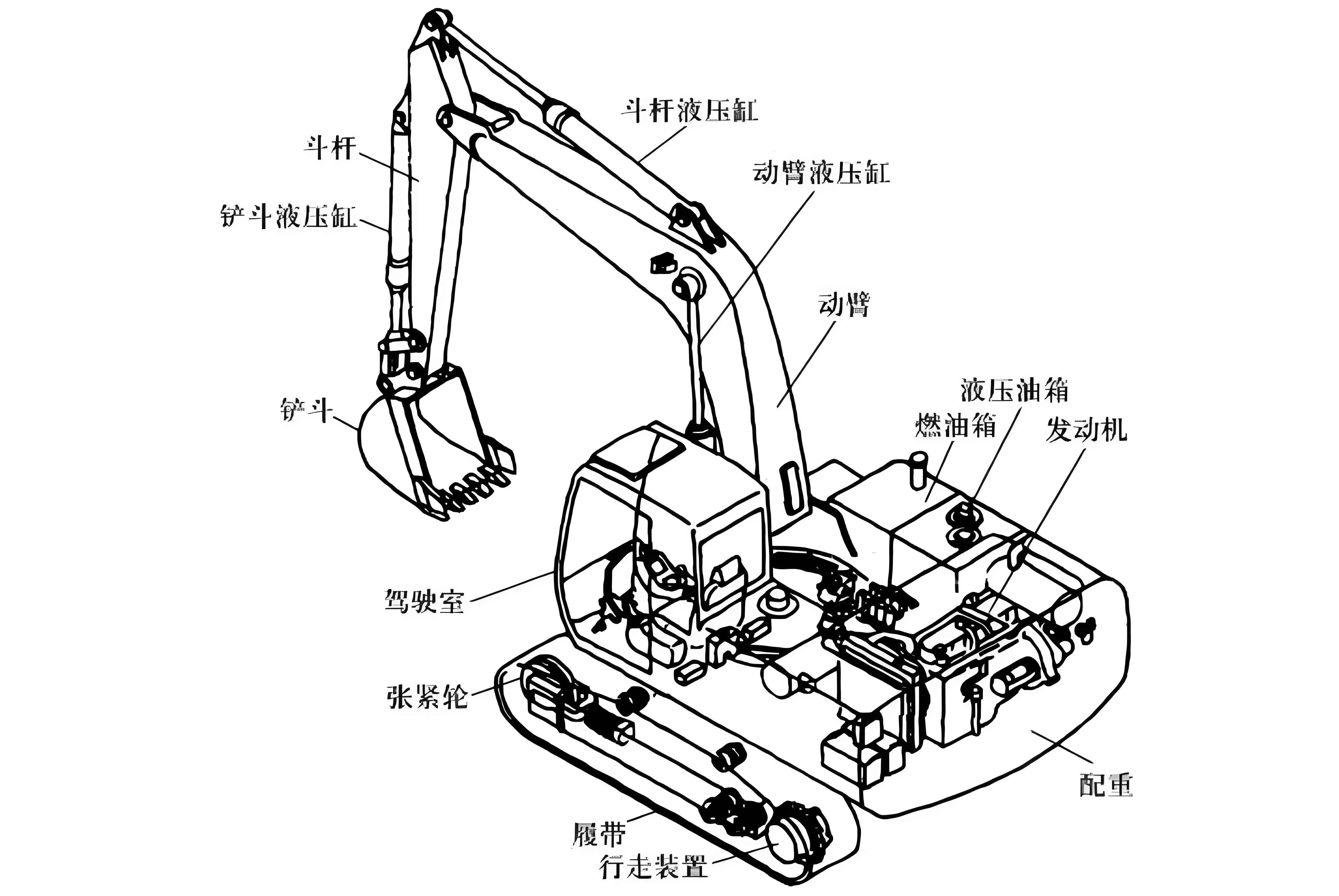
The working device of a hydraulic excavator mainly consists of a mechanical structure system and a hydraulic control system. The mechanical structure system includes the boom, arm, bucket, connecting rod, and rocker arm, etc. The hydraulic control system includes three sets of hydraulic cylinders and connecting pipes. The movement of the bucket tooth is realized by the coordinated movement of the hydraulic cylinders of the boom, arm, and bucket.
| Component | Description |
|---|---|
| Boom | The main part of the working device that provides the lifting force. |
| Arm | Connects the boom and the bucket, and provides the extending force. |
| Bucket | The end part of the working device that directly contacts the working object. |
| Hydraulic Cylinder | Provides the power for the movement of the working device. |
3. Kinematic Analysis of Excavator Working Device
3.1 Coordinate System Establishment
The D – H coordinate method is used to establish the coordinate system of the working device. The reference coordinate system is set at the hinge point of the boom and the slewing device, and the joint coordinate systems of the boom, arm, and bucket are established respectively.
3.2 Forward Kinematics Analysis
The forward kinematics analysis is to solve the transformation relationship from the joint space to the pose space of the bucket tooth. According to the D – H coordinate transformation matrix, the position and orientation of the bucket tooth in the base coordinate system can be obtained.
3.3 Inverse Kinematics Analysis
The inverse kinematics analysis is to solve the joint angles that can make the bucket tooth reach a certain pose. Using the geometric analysis method, the inverse kinematics equations of the working device are established, and the joint angles are solved.
4. Trajectory Planning Methods of Bucket Tooth
4.1 Cubic Interpolation Function
The cubic interpolation function is a commonly used trajectory planning method. It has the advantages of simple calculation and easy implementation. However, it also has the disadvantage of sudden acceleration change at the connection points of multiple segments.
4.2 Quintic Interpolation Function
The quintic interpolation function can ensure the smoothness of the trajectory by using more constraint conditions. But it requires more complex calculations and more given constraint conditions.
4.3 NURBS Curve
The NURBS curve combines the advantages of the Bézier curve and the non – rational B – spline curve. It has good local adjustability and can accurately express quadratic curves or surfaces. But it needs to calculate parameters such as node vectors, and the calculation is more complex.
| Trajectory Planning Method | Advantages | Disadvantages |
|---|---|---|
| Cubic Interpolation Function | Simple calculation, easy implementation | Sudden acceleration change at connection points |
| Quintic Interpolation Function | Smooth trajectory | Complex calculation, more constraint conditions |
| NURBS Curve | Good local adjustability, accurate expression | Complex calculation of node vectors |
5. Optimization of Trajectory Planning
5.1 Optimization Criteria
In the trajectory planning of the bucket tooth, common optimization criteria include energy consumption optimization, motion impact optimization, time optimization, and comprehensive optimization combining the above three. Considering the actual working conditions of the excavator, the comprehensive optimization of time and impact is often adopted.
5.2 Particle Swarm Optimization Algorithm
The particle swarm optimization algorithm is used to optimize the trajectory planning model. The algorithm has the advantages of simple iteration, fast convergence, and easy implementation. By setting the appropriate fitness function and parameters, the optimal trajectory can be obtained.
6. Trajectory Planning in Different Working Conditions
6.1 Ground Leveling Trajectory Planning
For the ground leveling operation, the cubic interpolation function, quintic interpolation function, and NURBS curve are used to plan the trajectory of the bucket tooth respectively. The results show that the quintic interpolation function and the NURBS curve can obtain a smoother trajectory.
6.2 Trench Excavation Trajectory Planning
In the trench excavation operation, the cubic interpolation function is optimized by using the particle swarm optimization algorithm. The optimization model is established with the minimization of joint impact and the optimization of time as the comprehensive optimization objectives. The results show that the optimized trajectory can reduce the joint impact and improve the working efficiency.
6.3 Trajectory Planning in Non – uniform Media
When excavating in non – uniform media, the bucket tooth may encounter obstacles. In this case, the obstacle is processed by using the circumscribed circle envelope method, and the trajectory is planned by using the particle swarm optimization algorithm with the length of the planned trajectory and the volume of the excavated medium as the comprehensive optimization objectives.
7. Joint Space to Stroke Space Conversion
The movement of the bucket tooth is realized by the coordinated movement of the hydraulic cylinders of the boom, arm, and bucket. Therefore, it is necessary to establish the conversion relationship between the joint space and the stroke space of the hydraulic cylinders. Using the geometric analysis method, the conversion functions from the joint angle space to the hydraulic cylinder stroke space of the boom, arm, and bucket are obtained respectively.
8. Simulation and Verification
8.1 AMEsim and MATLAB/Simulink Joint Simulation Model
In order to verify the accuracy of the trajectory planning model, an AMEsim and MATLAB/Simulink joint simulation model is established. The hydraulic system model and the mechanism model are built in AMEsim, and the control model is built in MATLAB/Simulink.
8.2 Simulation Results and Analysis
The simulation results show that the joint simulation model can accurately simulate the movement process of the excavator working device. By comparing the simulation results with the actual working conditions, the accuracy and effectiveness of the trajectory planning method are verified.
9. Conclusion and Future Work
9.1 Conclusion
This article focuses on the trajectory planning of the bucket tooth of the excavator working device. Through the kinematic analysis of the working device, the establishment of the trajectory planning model, and the optimization and verification of the model, a set of effective trajectory planning methods are obtained. The research results can improve the working efficiency and quality of the excavator, and have certain guiding significance for the intelligent development of the excavator.
9.2 Future Work
In the future, the following aspects can be further studied: (1) Considering the influence of the rotation movement of the working device on the trajectory planning of the bucket tooth; (2) Further optimizing the trajectory planning model to adapt to more complex working conditions; (3) Studying the interaction between the working device and the working environment to improve the adaptability of the excavator.