
As an engineer deeply involved in the development and implementation of advanced casting techniques, I have been part of a comprehensive trial production project focused on manufacturing flywheels using the lost foam casting process. The lost foam casting method, also known as evaporative pattern casting, is a precision technique that involves creating a foam pattern of the desired component, coating it with a refractory material, and embedding it in unbonded sand for casting. When molten metal is poured, the foam pattern vaporizes, allowing the metal to fill the cavity and form a precise replica. This approach is particularly advantageous for producing complex geometries with high dimensional accuracy and surface finish, making it ideal for components like flywheels that require full machining and rigorous performance standards. In this trial, we aimed to optimize the lost foam casting process to achieve a qualification rate exceeding 85% for flywheel castings, addressing common defects such as distortion, slag inclusion, and sand scabbing through systematic process controls.
The flywheel, a critical component in engine systems, demands defect-free casting to ensure operational reliability, dynamic balance, and longevity. Its structural simplicity belies the stringent requirements: full surface machining, internal soundness, and specific material properties. Through iterative testing and refinement in the lost foam casting workflow, we successfully enhanced production efficiency and casting quality. This article details the entire process from material selection to final shakeout, emphasizing the integration of technical parameters, empirical data, and first-hand insights to guide similar applications in industrial settings.
Technical Specifications and Material Requirements
In the lost foam casting of flywheels, adherence to technical specifications is paramount. The flywheel casting has a轮廓尺寸 of 274 mm in diameter and 32 mm in height, with wall thicknesses varying from 14 mm to 32 mm. The raw casting mass is 8.3 kg, and the material is HT250 gray iron, which must meet specific microstructural and mechanical criteria. Graphite length should fall within grades 4 to 7, with graphite morphology predominantly A and B types (A type constituting at least 70%, and no C type permitted). Ferrite content must be less than 10%, and hardness after surface machining to a depth of 1.5 mm should range from 187 to 241 HBS, with a hardness variation not exceeding 25 HBS. These requirements necessitate precise control over the lost foam casting process, particularly in foam pattern quality, coating application, and metal pouring parameters.
To quantify the material composition, we established strict chemical control ranges for HT250, as summarized in Table 1. This ensures consistent mechanical properties and minimizes variations that could lead to defects in the lost foam casting process.
| Element | Minimum (%) | Maximum (%) |
|---|---|---|
| Carbon (C) | 3.10 | 3.30 |
| Silicon (Si) | 1.85 | 2.40 |
| Manganese (Mn) | 0.60 | 0.95 |
| Phosphorus (P) | 0.070 | 0.10 |
| Sulfur (S) | 0.070 | 0.10 |
The successful implementation of lost foam casting for such specifications relies on a holistic approach, where each process step is optimized based on empirical data and theoretical principles. For instance, the density of the foam pattern directly impacts dimensional stability and gas evolution during pouring, which can be expressed using the formula for density control: $$\rho_{\text{foam}} = \frac{m_{\text{beads}}}{V_{\text{pattern}}}$$ where $\rho_{\text{foam}}$ is the target foam density (20–22 g/L), $m_{\text{beads}}$ is the mass of EPS beads, and $V_{\text{pattern}}$ is the volume of the molded pattern. By maintaining this density range, we reduce the risk of deformation and improve pattern integrity in the lost foam casting sequence.
Foam Pattern Production and Control
The foundation of high-quality lost foam casting lies in the foam pattern, which accounts for 50–60% of the process success. In this trial, we selected EPS (Expandable Polystyrene) material, specifically grade B106, for its consistent expansion properties and compatibility with lost foam casting applications. The pre-expansion of EPS beads was meticulously controlled to achieve a堆积 density of 18–20 g/L, which subsequently allows the molded foam pattern to attain a density of 20–22 g/L. This is critical because higher densities can lead to excessive gas generation during pouring, causing defects like porosity or slag inclusions, while lower densities may result in pattern collapse or distortion.
Pre-expansion was conducted using a specialized pre-expander, followed by a熟化 period of 4–8 hours in a conditioning chamber to stabilize the beads and allow for even moisture distribution. The熟化 process can be modeled using a diffusion equation: $$\frac{\partial C}{\partial t} = D \nabla^2 C$$ where $C$ represents the concentration of blowing agents or moisture, $D$ is the diffusion coefficient, and $t$ is time. By optimizing熟化 conditions, we ensure uniform bead size and reduce residual stresses in the final foam pattern.
For foam molding, we employed a hydraulic semi-automatic molding machine designed for lost foam casting, which enabled the production of flywheel patterns in a single piece. The molding parameters, including steam pressure, temperature, and cycle time, were calibrated to minimize variations. After molding, the patterns underwent natural aging at room temperature for 10–15 days to facilitate the diffusion and evaporation of residual moisture and blowing agents. This step is vital in lost foam casting to prevent surface defects and ensure dimensional accuracy during coating and casting.
Prior to assembly, each foam pattern and its corresponding gating system components were dried in an independent烘干室 at 40±5°C with relative humidity below 30%. This drying process eliminates moisture that could otherwise lead to steam-related defects during metal pouring. The drying kinetics can be described by Fick’s law of diffusion: $$J = -D \frac{\partial \phi}{\partial x}$$ where $J$ is the flux of moisture, $D$ is the diffusivity, and $\phi$ is the moisture concentration gradient. By monitoring weight loss and using moisture sensors, we verified that patterns were thoroughly dried before proceeding to the next stage of lost foam casting.
Pattern精整 involved meticulous trimming to remove flash and burrs, followed by surface repair using specialized tools. Only patterns that passed dimensional inspections were selected for assembly. The黏接 of foam patterns to the gating system was accomplished with hot melt adhesive, applied sparingly to minimize the introduction of foreign materials that could cause defects in the lost foam casting process. The assembly was designed to cluster 16 flywheels per gating system, optimizing production efficiency while maintaining quality standards.
Coating Application and Drying Optimization
In lost foam casting, the coating serves as a barrier between the foam pattern and the molten metal, preventing sand erosion and facilitating gas escape. We utilized a commercial refractory coating tailored for lost foam casting, which exhibited excellent permeability, adhesion, and thermal stability. The coating was applied in two layers to achieve a uniform thickness of 0.7–1.0 mm, as measured by ultrasonic gauges. This thickness range balances gas permeability and mechanical strength, which is crucial for preventing metal penetration and sand-related defects in lost foam casting.
The coating slurry was prepared with controlled viscosity and solid content, and its application was performed via dipping, followed by draining and drying. The drying process for each coated layer was conducted in a controlled environment to prevent cracking or delamination. The relationship between coating thickness and drying time can be approximated by: $$t_{\text{dry}} = k \cdot \delta^2$$ where $t_{\text{dry}}$ is the drying time, $k$ is a constant dependent on temperature and humidity, and $\delta$ is the coating thickness. By maintaining drying parameters within specified limits, we ensured coating integrity throughout the lost foam casting process.
Additionally, the coating’s composition was analyzed for key properties such as refractoriness and gas permeability, which are summarized in Table 2. These properties directly influence the quality of the final casting in lost foam casting, as they affect how well the coating withstands thermal shock and allows decomposition products to escape.
| Property | Target Value | Measurement Method |
|---|---|---|
| Viscosity | 40–50 seconds (Ford Cup #4) | Flow cup test |
| Solid Content | 65–70% by weight | Gravimetric analysis |
| Gas Permeability | ≥120 (ASTM standard) | Permeability tester |
| Refractoriness | >1600°C | Pyrometric cone test |
Gating System Design and Pouring Dynamics
The gating system in lost foam casting is a critical element that governs metal flow, filling patterns, and defect formation. For the flywheel castings, we designed an open gating system characterized by the relationship: $$F_{\text{sprue}} > F_{\text{runner}} > F_{\text{ingate}}$$ where $F$ denotes the cross-sectional area of each component. This design promotes laminar flow and reduces turbulence, minimizing the entrapment of air and slag. The ingates were positioned strategically to ensure uniform metal distribution and prevent hot spots that could lead to shrinkage or distortion in the lost foam casting process.
One gating system was configured to accommodate 16 flywheel patterns, with a total pouring time of 30–35 seconds. The pouring time can be calculated using the formula: $$t_{\text{pour}} = \frac{V_{\text{total}}}{Q}$$ where $V_{\text{total}}$ is the total volume of metal required (including the gating system), and $Q$ is the flow rate, which depends on the ladle geometry and pouring height. By controlling these parameters, we achieved consistent filling and reduced the likelihood of cold shuts or misruns in lost foam casting.
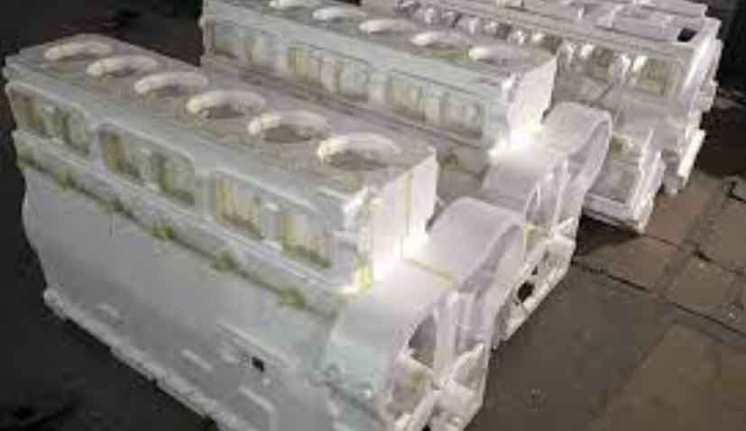
The illustration above depicts the gating system layout used in our lost foam casting trial, highlighting the arrangement of sprue, runners, and ingates to optimize metal flow for multiple flywheels. This configuration was validated through simulation software and practical trials, ensuring that the lost foam casting process met the required quality benchmarks.
Molding and Sand Compaction Techniques
In lost foam casting, the molding phase involves embedding the coated pattern assembly in dry sand, which provides support and allows for gas escape during pouring. We used silica sand with a grain size of 30–50 mesh, which offers a balance between permeability and compactability. The sand was free of binders and moisture to prevent gas generation and ensure easy shakeout after casting.
The molding process began with placing the pattern assembly in a dedicated flask, followed by the addition of sand in two stages. Initially, a base layer of sand approximately 120 mm thick was added and compacted using a pneumatic vibration table with adjustable frequency. The vibration parameters were optimized to achieve uniform sand density without damaging the foam pattern. The compaction time was controlled to 20–25 seconds, as excessive vibration can cause pattern deformation or coating damage in lost foam casting.
After the first sand layer, the pattern was covered, and a second layer of sand was added to ensure adequate吃砂量 (sand thickness around the pattern), typically exceeding 100 mm to prevent mold wall movement or bulging during pouring. The sand surface was leveled, and a plastic film was applied to create a seal, followed by a 20 mm layer of protective sand to secure the setup. The pouring cup was kept exposed to facilitate浇注. The entire process was documented with process cards for traceability, emphasizing the team-based nature of lost foam casting where coordination is essential.
The effectiveness of sand compaction can be evaluated using the relative density formula: $$\rho_{\text{sand}} = \frac{m_{\text{sand}}}{V_{\text{flask}}}$$ where $\rho_{\text{sand}}$ is the sand density, $m_{\text{sand}}$ is the mass of sand, and $V_{\text{flask}}$ is the flask volume. By maintaining consistent sand density, we reduce the risk of voids or uneven support that could lead to casting defects in lost foam casting.
Alloy Melting, Pouring, and Solidification Control
The melting of HT250 iron for lost foam casting was conducted in a 2.0-ton medium-frequency induction furnace, with strict control over temperature and composition. The tapping temperature was maintained between 1560–1580°C to ensure proper fluidity and reduce the risk of cold defects. Inoculation was performed using ferrosilicon (0.2–0.3% by weight) added during pouring to promote graphite formation and improve mechanical properties. The inoculation process can be described by the equation for nucleation rate: $$I = I_0 \exp\left(-\frac{\Delta G}{kT}\right)$$ where $I$ is the nucleation rate, $I_0$ is a pre-exponential factor, $\Delta G$ is the activation energy for nucleation, $k$ is Boltzmann’s constant, and $T$ is temperature. This ensures a fine graphite structure in the final casting, aligning with the lost foam casting requirements.
Pouring was executed using a preheated ladle, with the pouring cup positioned close to the ladle nozzle to minimize turbulence and oxidation. The pouring sequence started with a small stream to initiate foam vaporization, followed by a increased flow rate once black smoke indicated decomposition. The pouring was completed within the specified time frame, with a final metal temperature above 1480°C to prevent premature solidification. Vacuum assistance was applied at 0.020–0.030 MPa to enhance metal flow and remove decomposition products, a key advantage in lost foam casting for reducing slag inclusions.
After pouring, the castings were allowed to cool in the flask for 1.0 hour to ensure complete solidification and reduce thermal stresses. The cooling rate can be modeled using Fourier’s law of heat conduction: $$\frac{\partial T}{\partial t} = \alpha \nabla^2 T$$ where $T$ is temperature, $t$ is time, and $\alpha$ is the thermal diffusivity. By controlling the cooling environment, we minimize residual stresses and improve the dimensional stability of flywheels produced via lost foam casting.
Defect Analysis and Process Improvement
Throughout the lost foam casting trial, we monitored common defects such as distortion, slag inclusion, and sand scabbing, and implemented corrective measures based on root cause analysis. For instance, distortion often resulted from uneven foam density or improper sand compaction, which was addressed by standardizing pre-expansion and vibration parameters. Slag inclusion was minimized through optimized gating design and vacuum control, while sand scabbing was reduced by ensuring coating integrity and adequate sand support.
We also developed a defect tracking system, as summarized in Table 3, which correlates process variables with defect types in lost foam casting. This enables proactive adjustments and continuous improvement in production quality.
| Defect Type | Primary Causes | Corrective Actions |
|---|---|---|
| Distortion | Irregular foam density, inadequate aging | Control pre-expansion density; extend natural aging time |
| Slag Inclusion | Turbulent metal flow, excessive foam residues | Optimize gating system; maintain pouring temperature |
| Sand Scabbing | Insufficient coating thickness, poor sand compaction | Apply uniform coating; calibrate vibration parameters |
| Porosity | High foam density, inadequate vacuum | Reduce foam density; enhance vacuum levels |
By integrating these strategies, the lost foam casting process for flywheels achieved a significant reduction in defect rates, culminating in a qualification rate of over 85%. This outcome underscores the importance of systematic process control and interdisciplinary collaboration in lost foam casting applications.
Conclusion and Future Perspectives
The trial production of flywheels using lost foam casting has demonstrated the viability of this method for high-precision, fully machined components. Through rigorous control of foam pattern quality, coating application, gating design, and pouring parameters, we successfully mitigated common defects and elevated the qualification rate to meet industrial standards. The lost foam casting process, with its ability to produce complex shapes and maintain tight tolerances, offers a competitive edge in automotive and machinery sectors.
Looking ahead, further optimization in lost foam casting could involve advanced simulation tools for predicting metal flow and solidification, as well as the exploration of alternative foam materials to reduce environmental impact. Additionally, automation in pattern assembly and coating could enhance consistency and scalability. As lost foam casting continues to evolve, its application to a broader range of components holds promise for revolutionizing manufacturing efficiency and product quality.
In summary, the lost foam casting technique, when executed with precision and holistic management, proves to be a robust solution for producing demanding parts like flywheels. Our experience in this trial reinforces the value of integrated process engineering and sets a benchmark for future innovations in lost foam casting.