
According to the structural characteristics of the feeding rotor of the centrifugal casting machine, the transfer matrix method is used to analyze the dynamics of the rotor system of the centrifugal casting machine. Firstly, the rotor system is divided into N thin rigid disks without thickness but with mass and inertia, and N-1 shaft segments without mass. As shown in Figure 1, each disk and the common end shaft segment constitute a unit For the nth unit, the length of its shaft segment ln = 0.

Considering the support stiffness and damping, the force of the i-th disc is shown in Figure 2.

According to the force analysis, the motion differential equation of the disk can be written as follows:
In the xoz plane
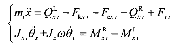
In the YOZ plane
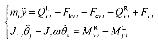
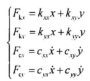
Where, & is the rotor speed, FK, FC and F are spring force, damping force and unbalanced centrifugal force respectively, and their subscripts X and y are in the xoz plane and. YOZ plane respectively, where the expressions of spring force and damping force are as follows:
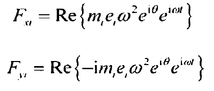
There is an eccentric mass on each section along the axis of the mold. The eccentric mass on the i-th disc can be expressed by the two parameters of eccentric distance EI, θ I and azimuth a, as shown in Fig. 3. Then the unbalanced centrifugal force on the i-th disc is expressed as:

The complex number is used to represent the state variables, and the transfer relationship between the two ends of the disk is written as:

It is abbreviated as follows:
The stress analysis of the i shaft segment is carried out, as shown in Figure 4.
