
Unit 2 of a certain power plant in Huaneng is a 300 MW supercritical coal-fired unit that was put into operation in October 1994. The turbine is equipped with two large cast steel high-pressure combined valves (one main valve and two control valves are integrated). The main steam valve disc adopts a vertical inverted structure, with a pressure gauge of 23.5 MPa and a design temperature of 540 ℃ in front of the main valve. The main steam valve housing is a large cast steel component, made of ZG15Cr1Mo1V material. The inlet chamber has a diameter of 800 mm and a thickness of 260 mm.
During the maintenance of Unit 2 in 2018, it was found that the large cast steel parts of the high-pressure combined steam valves on both sides had varying degrees of cracks and porosity defects, and only simple polishing treatment was carried out. During the maintenance period of the unit in April 2023, ultrasonic testing was conducted on the high-pressure large cast steel parts on the A and B sides of the combined steam valve distribution chamber. The test results showed that there was a crack of about 200mm in length at a depth of 30-40mm on the A side of the upper port, and a crack of about 1/2 circle in length at a depth of 20mm on the B side of the upper port. There was a cavity of about (100 × 20 × 40) mm on the inner side of the outer wall steam temperature measurement point, A cavity was found at 100mm left and right of the centerline of the outer wall steam temperature measurement point, which is suspected to match the inner wall steam temperature measurement point and the backup port. Further confirmation is needed; There is a complete circle of cracks on the upper edge of side B, which is 15-20 mm. In addition, it was found that there was a leakage at the external temperature measurement point of the large cast steel part of the main steam valve shell on side A, indicating that the internal crack had expanded and connected to the temperature measurement hole, resulting in severe cracking.
1. Analysis of crack causes
The material of the high-pressure combined main steam valve body for large cast steel parts is ZG15Cr1Mo1V, which is a high-performance low alloy pearlite heat-resistant steel that can work for a long time at 570 ℃. It is commonly used in the manufacturing of various cylinders, steam chambers, nozzle groups, and main steam valve shells. However, this type of steel casting has a large wall thickness and complex structure in large steel castings such as the main steam valve. During the casting process of the inner shell of large steel castings, the slag removal agent is not completely discharged, and there are casting defects such as pores, inclusions, and cold shuts. If the heat treatment and aging are not sufficient, the internal stress is not fully released, and under long-term high-temperature service and the alternating effect of start stop temperature, cracks are prone to occur in the defect and structural stress concentration areas.
2. Repair process and selection of welding materials
The repair welding of cracks in the main steam valve of large cast steel parts used to be carried out using homogeneous hot repair technology in the past. However, due to the cracks on the inner wall of the valve body in this project, the hot welding process must undergo welding preheating and post weld heat treatment, which is limited by the valve structure and cannot be implemented, and can easily cause deformation of the workpiece. The welding repair of cracks in large cast steel parts of the main steam valve body adopts nickel based welding repair process. In order to ensure repair quality and efficiency, the argon arc pulse welding process is adopted, and ENiCrMo-3 welding material is selected. The material of the main steam valve for large cast steel parts is ZG15Cr1Mo1V, and its chemical composition and mechanical properties at room temperature are shown in Tables 1 and 2.
| Element | C | Mn | Si | Cr | Mo | V | S | P |
| Content | 0.12~0.20 | 0.40~0.70 | 0.20~0.60 | 1.20~1.70 | 0.90~1.20 | 0.25~0.40 | ≤0.03 | ≤0.03 |
| Steel grade | Rm/MPa | Re/MPa | A/% | Z/%A | KV/J | HB |
| ZG15Cr1Mo1V | ≥490 | ≥343 | ≥14 | ≥30 | ≥29.4 | 140~200 |
The ENiCrMo-3 nickel matrix structure is a face centered cubic lattice structure. After being held at about 650 ℃ for a sufficient period of time, carbon particles and unstable quaternary phases are precipitated and transformed into stable Ni3 (Nb, Ti) rhombic lattice phase. After solid solution strengthening, the molybdenum and niobium in the nickel chromium matrix will improve the mechanical properties of the material. ENiCrMo-3 welding material is used to repair some important equipment, especially equipment operating under high temperature conditions. Its biggest feature is to effectively prevent “carbon migration” under high temperature conditions. Due to its linear expansion coefficient close to ZG15Cr1Mo1V, it can effectively reduce interface fatigue phenomenon caused by high temperature operation. At the same time, during the welding process, the combination of the weld metal and the base metal is not easy to form a brittle martensite layer near the fusion line, and has high strength in a wide temperature range. Nickel based welds have excellent plasticity, and stress is released by tapping without post weld heat treatment, making them suitable for the repair of such large steel castings. The chemical composition and room temperature mechanical properties of welding material ENiCrMo-3 are shown in Tables 3 and 4.
| Element | C | Mn | Si | Cr | Mo | V | S | Ni | P | Nb+Ta | Fe | Cu | Co | Al | Ti | W |
| Content | 0.23 | 0.35 | 0.096 | 21.59 | 8.65 | 0.014 | 0.001 | 64.8 | 0.001 | 3.654 | 0.69 | 0.036 | 0.035 | 0.13 | 0.156 | 0.036 |
| Welding materials | Rm/MPa | Re/MPa | δ5/% | HB |
| ENiCrMo-3 | ≥758 | ≥379 | ≥30 | 150~220 |
3. Repair plan and implementation process
3.1 Preparation work
Confirm that the work permit has been issued, and the large cast steel valve bodies on side A and side B have been disassembled. Adequate lighting for on-site work, completion of on-site protective installation, and preparation of tools and equipment. Set up suitable scaffolding on site and confirm that the air intake pipeline is well sealed. Take photos of various components of large cast steel valve bodies for archiving. Complete the raw material review, spectral inspection, macroscopic hardness inspection, surface penetration inspection, ultrasonic inspection of large cast steel valve bodies in the early stage, and record the original data.
3.2 Repair process
3.2.1 Preparation before repair
3.2.1.1 Inspection of valve bodies for large steel castings
(1) Conduct comprehensive magnetic particle or penetration testing on the inner wall of the valve body of large steel castings, especially near cracks, to determine the location and size of all cracks and other exposed defects in large steel castings.
(2) The outer wall of large cast steel valve bodies (especially at the corresponding crack location) should be subjected to magnetic particle or penetration testing according to the actual situation on site.
(3) Ultrasonic testing is performed on the defects of large steel castings inside the valve body corresponding to the crack location, to determine whether there are other defects in large steel castings that affect repair near the repair welding area, which is beneficial for internal quality acceptance after repair.
(4) Perform spectral material review and surface hardness testing on the location and adjacent areas of the crack.
3.2.1.2 Crack removal
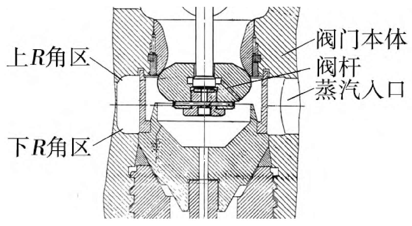
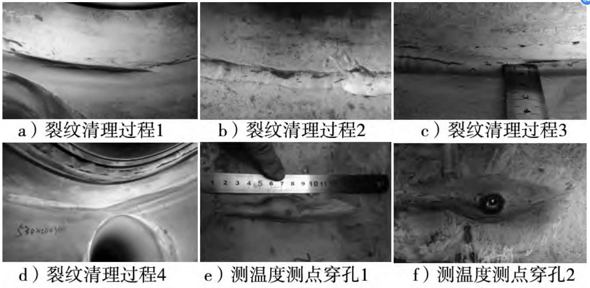
After ultrasonic testing was used to determine the crack area of a large cast steel valve body, the cracks concentrated in the upper and lower R corner areas of the steam inlet inner cavity of the large cast steel valve body, especially in the upper R corner area (Figure 1). Using an angle grinder and a rotary file to polish and open the crack depth area, the crack position is determined through surface dye penetrant testing. The crack is cleaned and polished to eliminate it, with a depth of 15-30 mm and a length of 50 mm. During the cleaning and polishing process, cracks expand and extend in some areas. During the polishing process, areas with discontinuous cracks are continuously cleaned, and finally surface dye penetrant testing is carried out to confirm the crack elimination situation, Until all cracks are eliminated. The crack cleaning process is shown in Figure 2.
3.2.2 Welding groove form
The groove is prepared by mechanical processing. Considering that the welding of workpieces should minimize the workload while ensuring smooth welding, the groove shape introduced in DLT 753-2001 “Technical Guidelines for Repair Welding of Steam Turbine Steel Castings” and JBT 5263-2005 “Technical Conditions for Power Plant Valve Steel Castings” was not used for groove welding. Instead, the groove shape was slightly widened after eliminating cracks, and the sharp corners transitioned smoothly to ensure that the welding personnel could weld normally.
After the groove processing is completed, the entire welding area needs to be subjected to penetration testing to ensure that there are no potential defects in large steel castings. Use an angle grinder to clean rust and expose metallic luster within a 30 mm range around the groove.
Before welding, remove moisture, oil stains, and inspection agents from the welding surface of the base metal groove.
3.2.3 Welding materials
Select ENiCrMo-3 nickel based alloy welding wire with specifications Φ 1.6 mm/ Φ 2.5 mm.
3.3 Welding process
The argon arc pulse welding process is adopted, and the welding material specifications and welding specifications are shown in Table 5.
| Welding material specifications | Φ 1.6 mm | Φ 2.5 mm |
| Current/A | 90-130 | 120-175 |
| Voltage/V | 14-18 | 15-20 |
| Polarity | DC reverse connection | DC reverse connection |
The use of nickel based welding method requires the use of low current during welding. Choosing a current that is too small will reduce the welding speed and increase the welding line energy. Therefore, while ensuring the welding speed, choose a suitable low current for welding.
Preheating method before welding: Use an oxygen acetylene gun to preheat the groove and its surrounding temperature to 80-100 ℃, during which the nickel based welding wire has good deposition performance.
4. Welding process
Bottom layer selection Φ Welding 2-3 layers with 1.6 mm welding wire, using low current welding for continuous welding. The front and rear weld beads should be staggered by a certain distance, and the filling layer should be selected Φ 2.5 mm welding wire covers the surface of the groove.
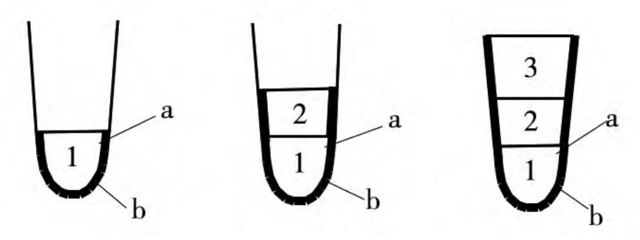
When welding the groove, due to the narrow and deep shape of the groove, it is not possible to complete the welding of the bottom layer at once. The welding of the bottom layer and the filling layer adopts a multi-layer and multi pass welding method (Figure 3), where a is the filling layer and b is the bottom layer.
The temperature measurement hole perforation is sealed using a sealing method, and after the sealing is completed, it is inspected to detect whether there are defects in large steel castings.


After each section of the base layer is welded, the operator should observe the base layer in a timely manner to check for small hot cracks and incomplete fusion with the substrate. If defects are found in large steel castings, they should be dealt with in a timely manner. After the treatment is completed, preheating should be carried out again before welding operations. When welding the filling layer, attention should be paid to the staggered distribution of weld beads, the joints should be staggered by a certain distance, and attention should be paid to the control of interlayer temperature. After each welding pass, mechanical hammering should be used to eliminate stress. On site, DCZC22 rechargeable brushless impact hammer should be used, with a low-speed first gear and a round headed drill rod used for impact hammering. The hammering should be done in the order of first hitting the middle of the weld pass, and then hitting both sides of the weld pass. The hammering should be compact and neat to avoid repetition. After hammering, the welds on both sides should be inspected to confirm that there are no defects. Figure 4 shows overlapping defects, Figure 5 shows incomplete fusion defects, Figure 6 shows void defects, and Figure 7 shows the surface of the weld after hammering.


5. Quality inspection
After cooling the weld temperature to room temperature, polish the welding area to restore surface shape and roughness. Perform surface dye penetrant testing on all welding positions and adjacent areas of the repaired surface or near surface welded large steel castings, in accordance with NB/T 47013-2015 “Non destructive Testing of Pressure Equipment”. The inspection standard is to have no cracks or other types of defects above level II.
All repair areas and the internal areas of adjacent large steel casting valve bodies shall be subjected to ultrasonic testing to determine whether there are harmful defects such as cracks caused by welding in the vicinity of the welding area. The inspection shall be accepted according to the relevant ultrasonic testing methods in GB/T7233-1987 “Ultrasonic Testing and Quality Rating of Steel Castings”.
6. Conclusion
The on-site repair of a large cast steel component for the high-pressure main steam valve body of a 300 MW supercritical unit is a successful case of ZG15Cr1Mo1V large cast steel material crack repair, which confirms the feasibility of on-site repair of internal component defects in large cast steel components and can meet the requirements of unit use. This technology is easy to operate in actual construction and has certain promotional value in engineering practice.