
With the development of intelligent and lightweight rail vehicles, higher requirements are put forward for the compactness and lightness of vehicle braking system components. On the premise of meeting braking performance and compact space, the load-bearing components are optimized through topology to achieve weight reduction, and on the other hand, higher strength materials are used to meet the strength performance requirements of the components. After topology optimization, the original castings of the clamp were transformed from ductile iron to E-grade steel castings for locomotives and vehicles. The casting defects that are prone to occur in steel castings have an impact on strength, and this impact is evaluated in the article.
1. Analysis of stress conditions for steel castings used in clamps
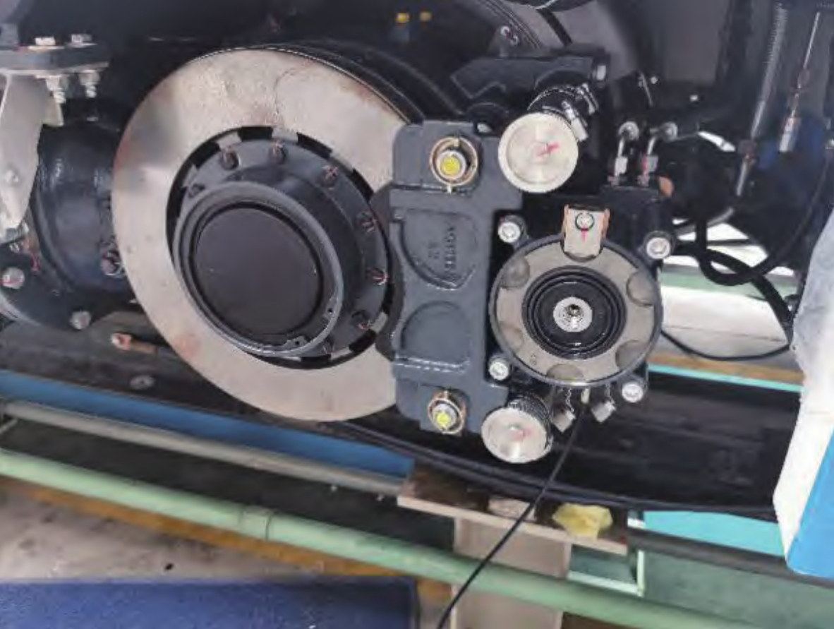
The hydraulic brake caliper, as the executing component of the braking system, is shown in Figure 1. It bears the dynamic load and impact force of the brake disc during the braking process.
The clamp main frame structure – the bracket is a steel casting component, and after structural optimization, its weight is reduced by 32%. The stress condition is shown in Figure 2. On the one hand, the bracket bears the axial clamping force formed by the lever applied to the brake disc; On the other hand, it is subjected to tangential friction from the brake disc.
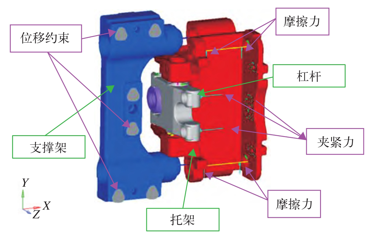
Based on the force conditions of the clamp, first simulate the clamp using the pre-processing software HyperMesh, the solver using OptiStruct, and the simulation using second-order tetrahedral elements; The loading and constraint method is shown in Figure 2. The clamping force is applied vertically to the contact surface between the lever and the bracket, the frictional force is applied to the installation hole of the bracket, and the displacement constraint is at the installation interface between the support bracket and the vehicle.
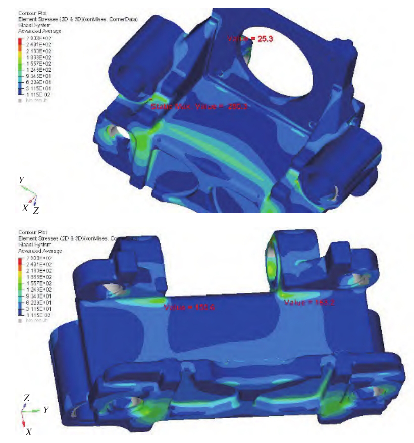
The stress cloud diagram of the bracket is shown in Figure 3. The simulation results under static strength calculation conditions show that the maximum strength stress value of the bracket is 280 3 MPa. At present, steel castings for clamps mostly use QT500/QT600 materials, and the performance parameters are shown in Table 1.
| Material | Elastic modulus/GPa | Poisson’s ratio | Tensile strength/MPa | Yield strength/MPa |
| QT500-7 | 162 | 0.3 | 500 | 320 |
| QT600-7 | 162 | 0.3 | 600 | 370 |
| E-grade steel | 172 | 0.3 | 830 | 690 |
According to the static strength evaluation method, under static load conditions, the utilization coefficient of each part of the structure should be less than or equal to 1, and the utilization coefficient is equation (1):
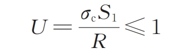
In the formula: U is the utilization coefficient; S1 is the safety factor for yield or elastic strength; R is the yield or 0 of the material 2% elastic ultimate stress, MPa; σ C is the calculated stress, MPa.
(1) QT600-7 strength verification:
(2) Strength verification of E-grade steel:
After strength verification, the ductile iron material cannot meet the static strength requirements, while the utilization coefficient of E-grade steel is less than 1, which can meet the static strength requirements of the bracket.
2. Evaluation of the impact of defects in E-grade steel castings on strength
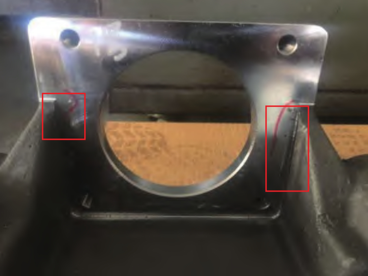
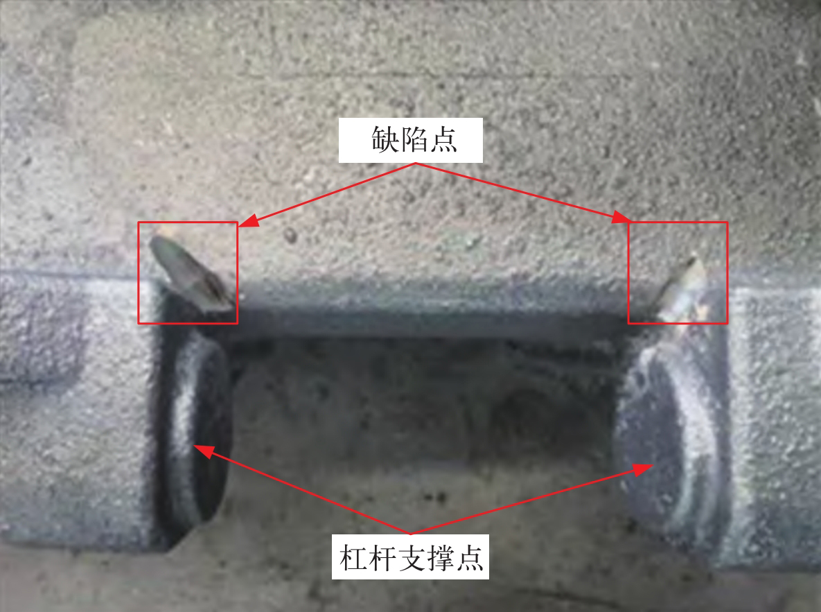
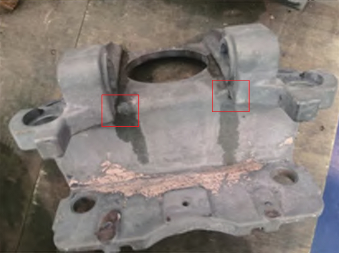
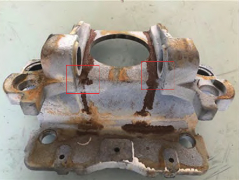
Unlike ductile iron, steel casting materials are prone to defects such as shrinkage, sand holes, and slag inclusion during the casting process for complex structural components due to their inherent characteristics such as large shrinkage and poor fluidity during casting. The structural characteristics of the aforementioned bracket are relatively complex. Although the design optimization of the pouring system and the reasonable placement of internal and external cold iron can avoid defects at some large stress points, there are still some areas with casting defects. There are several slag inclusions in the four threaded interface planes of the bracket (as shown in the box), as shown in Figure 4. The simulated stress value in this area is 25 3 MPa belongs to the low stress risk area, so there is no need for welding repair treatment. During the rough stage of the bracket, it was found that there was a shrinkage defect at the bottom corner near the lever support (as shown in the diagram before welding repair after defect treatment), as shown in Figure 5. From its characteristic point of force, it can be seen that during the clamp braking process, the lever connection, as the lever fulcrum, bears a large tensile stress. If there are casting defects, they may extend inward during the long-term repeated force process, which may lead to fatigue failure risk. The simulated stress value in this area is 163 2 MPa belongs to the medium stress risk area. As the junction of three surfaces, the defect is difficult to solve in steel casting technology, so it is necessary to consider using welding repair technology to compensate for the defect problem. However, E-grade steel, as a high-strength steel with high carbon content, has poor weldability. The crack source of weld defects is prone to stress concentration, leading to crack source propagation and structural damage, Further testing is needed to verify whether the bracket after welding can withstand issues such as strength and impact during the use of the clamp.
3. Experimental verification of welding repair defects
Evaluate the reliability of E-grade steel welded brackets from three aspects: static strength, impact, and fatigue strength tests:
(1) Static strength test analysis
According to the requirements of ISO 11970 “Process Specification and Evaluation of Cast Steel Welding Products” for E-grade steel base metal welding test plates, the processed test pieces are shown in Figure 6. The welding adopts a multi pass and multi-layer welding method, and the welding rod selects E8515 with a strength level not lower than the base metal; The test plate is preheated to 300 ℃ and insulated for 2-3 hours before welding, with an interlayer temperature of 200-300 ℃. After welding, it is subjected to annealing heat treatment: heating to 500 ℃, insulation for 2-3 hours, and then taken out for air cooling.
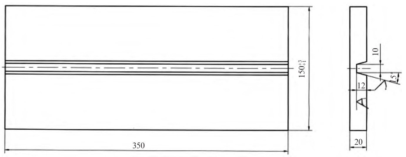
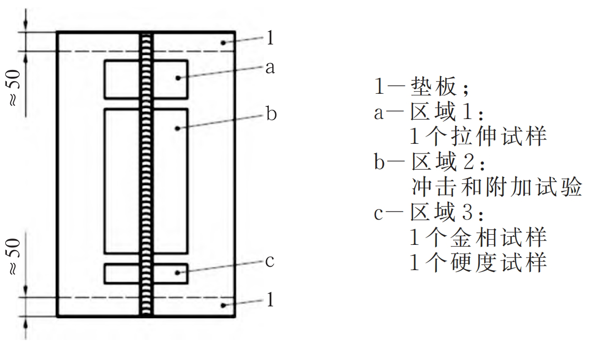
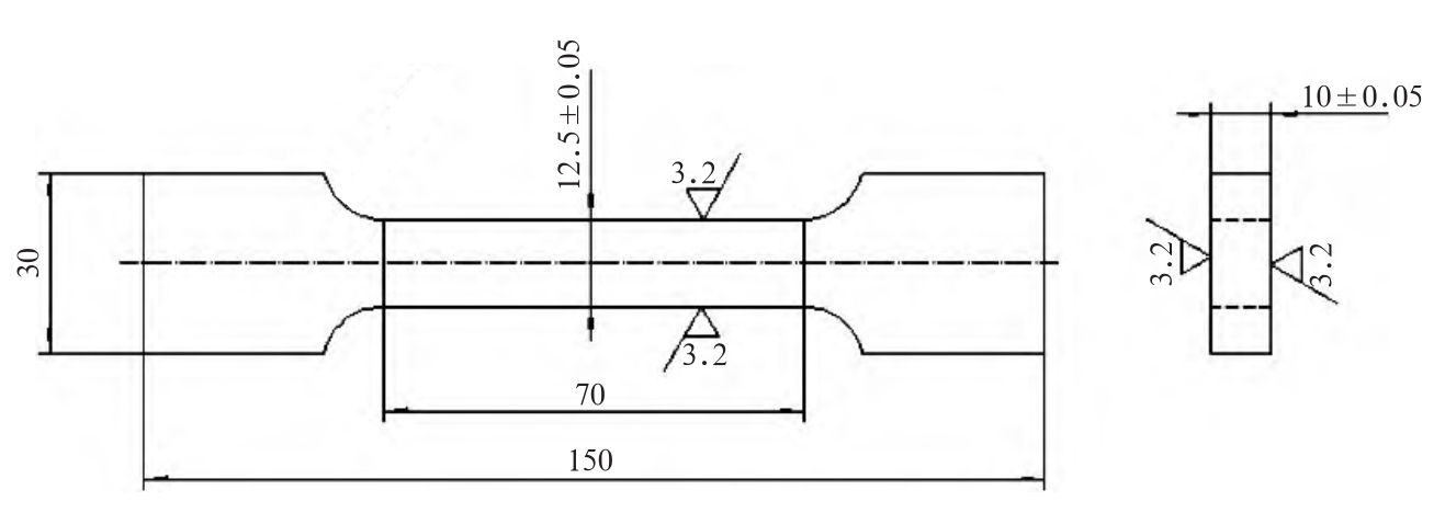
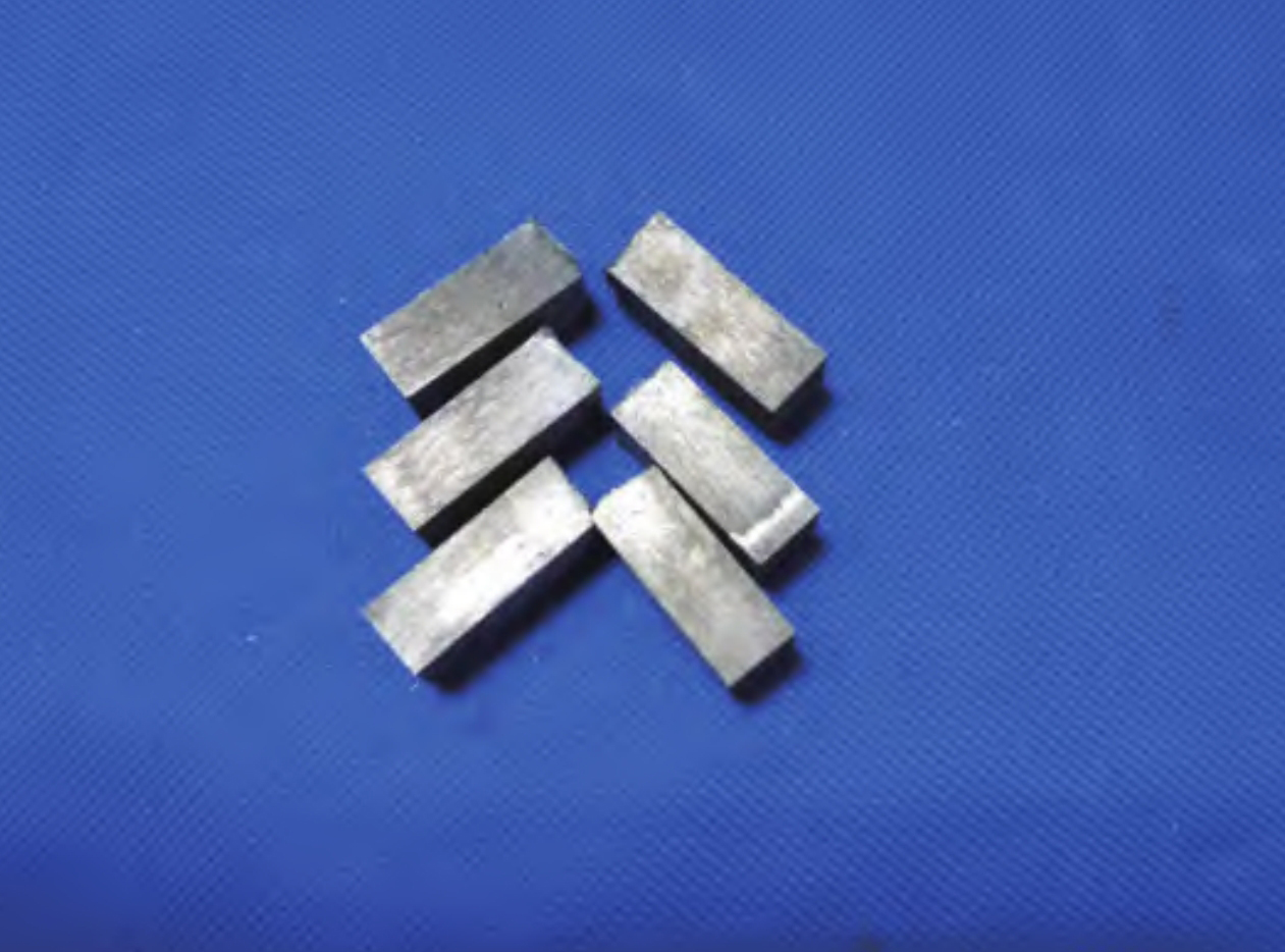
The sampling position of the tensile specimen is shown in Figure 7, and two tensile specimens are taken. Tensile specimen 1: full weld seam; Tensile sample 2: Half of the weld and half of the base metal, with sample dimensions shown in Figure 8.
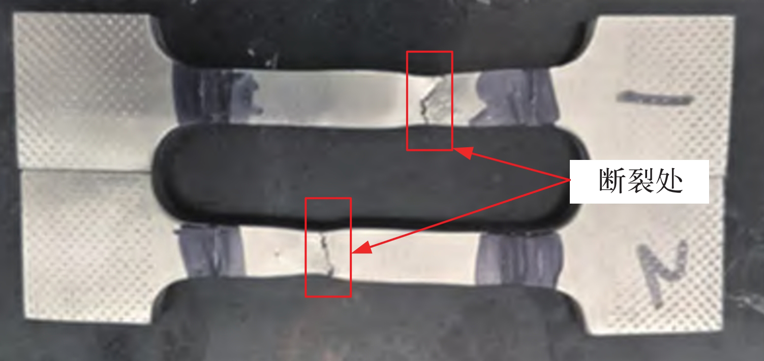
After welding, the specimen underwent a tensile test, and the fracture situation is shown in Figure 9. It can be seen that the fracture position is not at the weld seam.
The tensile strength is slightly lower than that of the base material, as shown in Table 2, but meets the requirements of ISO 11970 (with an allowable deviation of 5%), and the difference between the data obtained from Table 1 and the base material is not more than 2%. Therefore, based on the above analysis, the static strength of E-grade steel after welding repair was not significantly affected by the weld seam.
| Name Performance | Tensile strength/MPa | Yield strength/MPa | Elongation rate/% | Section shrinkage/% |
| No.1 test block | 827 | 809.6 | 13.8 | 34.1 |
| No.2 test block | 820.1 | 733.4 | 14.6 | 36 |
| Base material requirements | ≥830 | ≥690 | ≥14 | ≥30 |
(2) Impact test analysis
① Impact testing of test blocks
According to the requirements of ISO 148-1:2016 “Metallic materials – Charpy pendulum impact test – Part 1: Test method (E)”, several impact test blocks are processed, with 50% of the weld and 50% of the base material thickness. The post impact test block is shown in Figure 10, and the impact test results are shown in Table 3. From Table 3, it can be seen that the average impact energy of the test block is 39 Around 5 J can meet the requirement of not less than 27 J for the base metal, so there is no decrease in the impact performance of the test block after welding repair.
| Test items | Test conditions | Result KV2/J | Average/J |
| Impact absorption capacity | Charpy V-notch Test block size: 10 mm x 10 mm x 55 mm | 42.5 37.5 39 | 39.5 |
| / | / | Base material requirements | 27 |
② Impact test of bracket
In order to verify the impact of welding repair on the bracket under actual impact conditions, a complete set of assembled clamps were used as test specimens for impact vibration testing. According to the requirements of industry IEC 61373-2010 “Railway Equipment – Rolling Stock Equipment – Impact and Vibration Tests”, Class II impact vibration tests were conducted on the clamps installed on the bogie frame. Vertical, horizontal, and longitudinal simulated long life tests, impact tests, and functional random tests were carried out to enhance the magnitude of random vibration, as shown in Figure 11.
After completing the impact vibration test, the clamp was disassembled as shown in Figure 12, and no obvious deformation or cracking occurred at the welded joint of the bracket.
(3) Fatigue test analysis
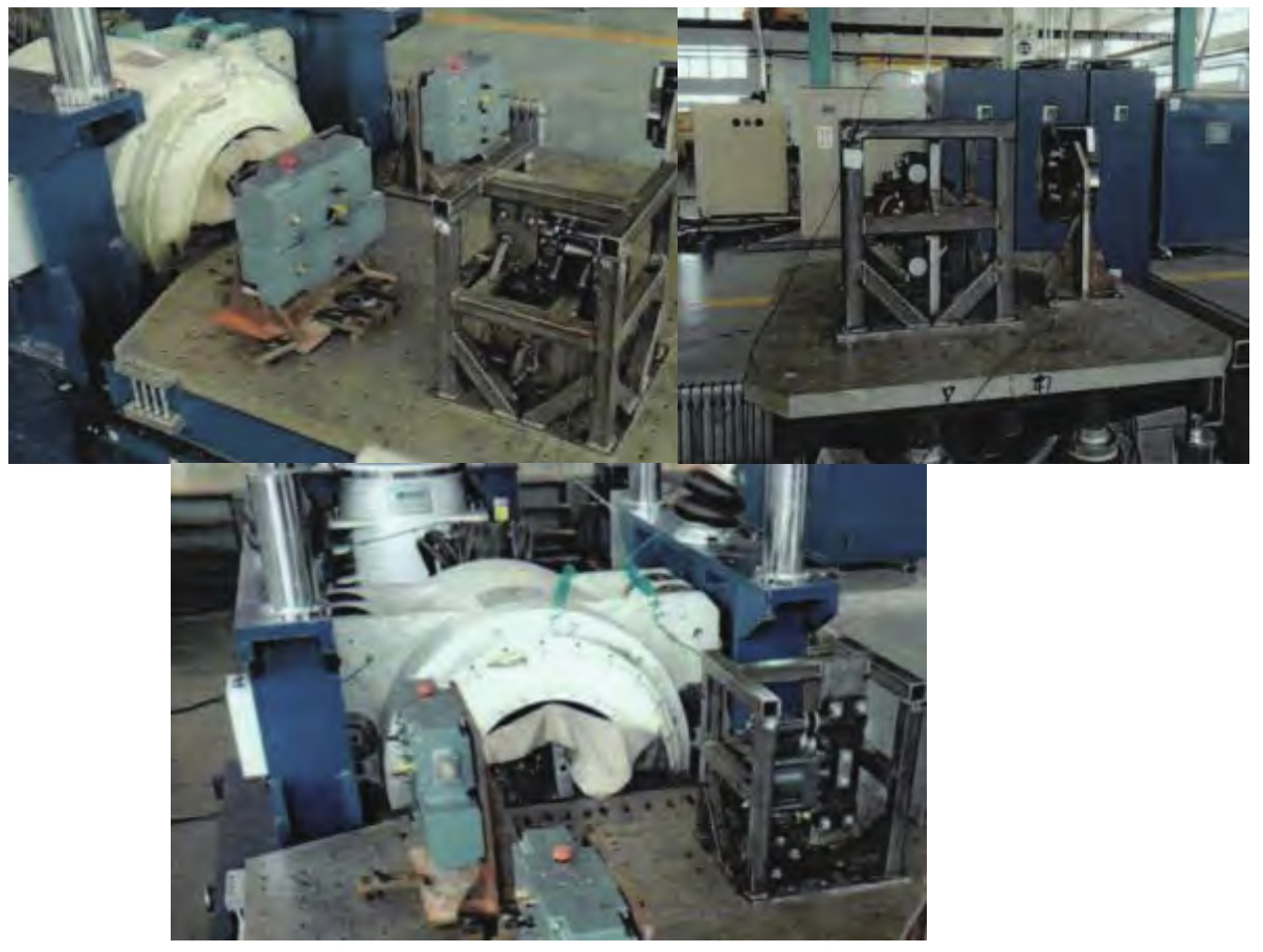
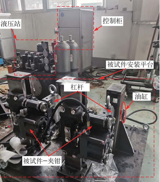
In order to verify the fatigue strength of the welded bracket, the assembled complete set of clamps was used as the test piece, and a fatigue strength test bench was built. The clamp fatigue test bench is shown in Figure 13, consisting of an electrical control cabinet, hydraulic pump station, test piece installation platform, connecting pipelines, etc. The electrical control cabinet is used to output control signals and control the pressure of the hydraulic pump station, thereby outputting the desired target oil pressure; The installation interface position of the clamp applied to the installation platform is the same as that on the vehicle. It simulates the brake disc as a lever structure, and applies force to the lever through the oil cylinder, which is then converted into torque to the clamp to simulate the torque of the brake disc under braking conditions. Therefore, the fatigue test bench can use the clamping force of the clamp itself and the torque of the lever when the test piece clamp is applied, To achieve strength testing of the composite clamping force and radial friction force of the bracket.
Based on the full life cycle of the product, 2 million fatigue tests were conducted on the clamp. After the tests, the clamp was disassembled and there were no deformation or fracture issues with the bracket. In order to verify whether there were micro cracks in the welded joints of the bracket after the fatigue test, magnetic powder testing was performed on the bracket, as shown in Figure 14. The test results showed that no cracks were found at the welded joints.
4. Conclusion
ZHY Casting is based on the fact that complex steel castings made of E-grade steel materials for locomotives and vehicles are prone to casting defects such as shrinkage and slag inclusion. Theoretical simulation methods are used to classify the stress zone levels of steel castings and evaluate the required welding repair areas; For areas with high stress and prone to defects, welding repair treatment is required. The welding repair bracket is tested and verified from three aspects: static strength specimen tensile test, specimen and bracket impact test, and whole machine clamp fatigue test. The results show that the tensile fracture of E-grade steel parts after welding repair treatment did not occur at the welding repair site; The impact energy of the test block can still meet the material standard requirements, and there are no defects such as deformation or cracks at the welded joints after the impact vibration of the test piece; The fatigue strength test results of simulating actual vehicle working conditions indicate that there is no crack propagation phenomenon at the weld seam after long-term durability testing. The theoretical experimental research in the article provides a certain reference basis for the evaluation of defects in steel castings of high-strength steels such as E-grade steel; This provides feasibility for optimizing the structural topology of steel castings to reduce weight and solving strength problems with high-strength steel.