
In my production practice, I have relied on 3D printing sand casting technology to solve difficult thin-wall iron casting problems. One of the most representative parts is a narrow flow channel impeller made of HT250 gray cast iron. The casting has a mass of 16 kg, a maximum outside diameter of 339 mm, a height of 96 mm, a minimum blade wall thickness of only 2 mm, a cover plate wall thickness of 5 mm, and an outlet width of 6±0.2 mm. These dimensions place the part in the category of narrow channel impellers, where the outlet width is within 4-8 mm while the outer diameter is greater than 300 mm. This structural combination creates a difficult casting condition: the sand core is thin and weak, the venting path is restricted, and the filling of the thin cover and blade sections must be completed before the molten iron loses fluidity.
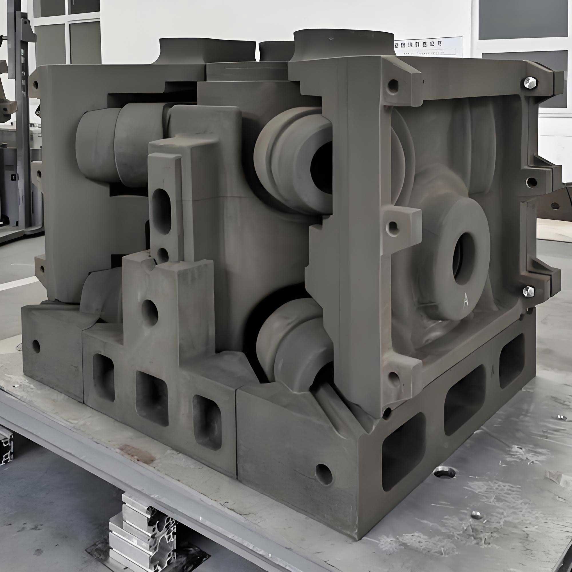
In my view, 3D printing sand casting is not only a method for making molds without tooling. It is also a way to reshape the design of the casting process. The narrow flow channel impeller used to be impossible to cast reliably because the blade sand core had to be assembled from several pieces or because the tooling could not extract the core. With 3D printing sand casting, I could print the entire blade sand core as one body. This eliminated assembly errors and improved the dimensional accuracy of the flow channel. In this article, I summarize my experience with two process schemes, explain why the vertical casting scheme succeeded, and discuss the advantages of 3D printing sand casting for this type of impeller.
1. Technical Requirements of the Impeller
The impeller is intended for a fluid-handling machine and therefore must have good surface quality and accurate flow passages. The casting drawing imposed strict requirements. The material is HT250 gray cast iron. The casting weight is 16 kg. The maximum outside diameter is 339 mm and the total height is 96 mm. The minimum blade wall thickness is 2 mm. The cover plate wall thickness is 5 mm. The outlet width, which is the most important flow passage dimension, must be maintained at 6±0.2 mm. The dimensional tolerance of the overflow surface must not be lower than CT9. The casting must not have cold shuts, sand adhesion, cracks, blowholes, slag inclusions, or shrinkage defects.
| Material | HT250 gray cast iron |
| Casting mass | 16 kg |
| Maximum outside diameter | 339 mm |
| Height | 96 mm |
| Minimum blade wall thickness | 2 mm |
| Cover plate wall thickness | 5 mm |
| Outlet width | 6±0.2 mm |
| Dimensional tolerance | CT9 or better |
| Flow channel quality | No cold shut, sand adhesion, cracks, blowholes, slag inclusions, or shrinkage |
From these requirements, I understood that the casting process must achieve three objectives. First, the filling must be stable and fast enough to reproduce the 2 mm thick blades. Second, the sand core must have adequate strength and rigid support so that it does not bend, shift, or crack. Third, the mold and core must have reliable venting so that gas does not remain trapped inside the narrow flow channel. These three objectives guided all subsequent decisions in my 3D printing sand casting process design.
For an initial estimate, I calculated the volume of the impeller casting using the liquid iron density:
$$V_{\text{casting}} = \frac{m_{\text{casting}}}{\rho_{\text{Fe}}}$$
Taking \(\rho_{\text{Fe}} = 7.0 \times 10^3 \ \text{kg/m}^3\), the volume is approximately:
$$V_{\text{casting}} = \frac{16 \ \text{kg}}{7.0 \times 10^3 \ \text{kg/m}^3} \approx 2.29 \times 10^{-3} \ \text{m}^3$$
The thin blade has a much smaller volume but a very large surface area. Therefore, the solidification process is dominated by the blade sections. A thin blade can freeze quickly, and if the metal front becomes turbulent or if gas pressure blocks the flow, a cold shut or misrun can easily occur.
2. Wall Thickness Analysis and Solidification Characteristics
Before choosing the casting process, I performed a wall thickness analysis. The casting has a maximum wall thickness at the cover plate of about 5 mm and a minimum blade wall thickness of only 2 mm. The ratio of cover plate thickness to blade thickness is small, but the absolute wall thickness is small for a gray iron casting of 339 mm diameter. This means that the casting has to be filled quickly in order to avoid premature solidification.
For metal solidification, the local solidification time is often estimated with Chvorinov’s rule:
$$t_{\text{solid}} = C \left( \frac{V}{A} \right)^2$$
where \(V\) is the volume, \(A\) is the cooling surface area, and \(C\) is a mold constant. The term \(V/A\) is called the solidification modulus. For a flat plate, the modulus is roughly half of the plate thickness. For the 2 mm blade, this gives:
$$M_{\text{blade}} \approx \frac{t_{\text{blade}}}{2} = \frac{2 \ \text{mm}}{2} = 1 \ \text{mm}$$
This is a very small modulus. In practice, it means that the molten iron in the blade channel loses superheat quickly. I therefore set the pouring parameters to ensure that the metal enters the cavity at a high temperature and that the filling time is short. My target was a pouring temperature of about 1430 °C and a pouring time of about 8 seconds.
The flow channel itself is narrow. The outlet width is 6±0.2 mm, and the blade spacing is very small. The hydraulic diameter of such a channel is small, and the resistance to molten metal flow is high. This is another reason why the gating system must be designed carefully. In my experience, a narrow flow channel impeller cannot be treated as a normal gray iron casting. It behaves more like a thin-walled casting with difficult feeding and venting paths.
3. Casting Process Design: Two Schemes
Because I was using 3D printing sand casting, I did not need to commit to a costly metal pattern before proving the process. I was able to test two different casting process schemes. The first scheme, which I call Plan A, was based on a conventional horizontal casting arrangement. The second scheme, Plan B, used a vertical casting arrangement specifically designed to improve filling and venting of the thin blade core.
| Item | Plan A | Plan B |
| Pouring position | Horizontal or flat position | Vertical pouring position |
| Mold structure | Upper and lower sand molds | Side cover wall cores and central blade core |
| Gating system | Stepped gating with bottom injection | Closed gating system with central injection between cover plates |
| Riser and vent design | Overflow risers, top sprue, venting fins at blade/cover joint | Top overflow riser, central core vent, top exhaust to atmosphere |
| Core behavior | Thin horizontal blade core may bend or shift | Vertical blade core is supported and easier to vent |
| Simulation result | High gas pressure in last filled areas | Stable filling and reduced air entrapment risk |
3.1 Plan A: Horizontal casting with stepped gating
In Plan A, I placed the impeller in the horizontal orientation. The casting process design included a stepped pouring system with bottom injection to fill the cavity smoothly. A top sprue was used to help fill the thin cover plate. I also added overflow risers and feeding risers for venting and compensation. At the connections between the blades and the cover plate, I placed thin venting fins. The sand mold was divided into upper and lower parts. The positioning was achieved by ring-shaped bosses and matching grooves. A core vent was provided at the inner circular hole.
The intention was to produce a stable bottom-filled cavity with enough top venting for the thin cover. In simulation, however, I observed that the last-filled regions still contained trapped gas. The horizontal blade core created large flat regions beneath the cover plate, and gas could not escape easily. In addition, the thin blade sand core had a long horizontal span. When molten iron surrounded it, the metallostatic pressure could bend the core, causing core shift and sand inclusions.
For a horizontal core, the bending moment can be estimated by a simply supported beam model:
$$M_{\text{bending}} = \frac{q L^2}{8}$$
where \(q\) is the uniform load from the molten iron and \(L\) is the unsupported length of the blade core. For a 339 mm diameter impeller, the unsupported length of the thin core is large. The bending stress is:
$$\sigma_{\text{bending}} = \frac{M_{\text{bending}}}{Z}$$
where \(Z\) is the section modulus of the sand core. Because the core is only 2 mm thick, its section modulus is very small. The result is a high risk of core cracking or deflection. This risk is difficult to control even with 3D printing sand casting.
3.2 Plan B: Vertical casting with closed gating
For Plan B, I changed the orientation and the gating strategy. I arranged the impeller so that the cover plates were vertical. The mold consisted of two side cover wall cores and a central blade core. The central blade core was printed as one whole body. I designed a closed gating system, with the gates entering from the middle between the two cover plates. A top overflow riser was placed at the highest point of the casting. The central circular area of the blade core had a vent that connected to the side wall core. The top vent opened directly to the atmosphere, providing a clear path for gas to escape.
This vertical arrangement has several advantages. First, the thin blade core is oriented vertically, which reduces the unsupported horizontal span. Second, the gas generated by the sand core can rise upward and escape through the top vents instead of being trapped under a horizontal cover plate. Third, the metal is injected from the center of the casting and flows outward and upward, which promotes progressive filling of the thin blade passages. Fourth, a closed gating system keeps the sprue and runner full of metal, preventing aspiration of air and reducing oxidation of the molten iron.
The closed gating system can be represented by the cross-sectional area relationship:
$$A_{\text{gate}} < A_{\text{runner}} < A_{\text{sprue}}$$
This means that the choke section is at the inner gates. The velocity at the gate can be estimated from the effective pouring head:
$$v_{\text{gate}} = \varphi \sqrt{2 g h_{\text{eff}}}$$
where \(\varphi\) is a friction loss coefficient, \(g\) is gravitational acceleration, and \(h_{\text{eff}}\) is the effective metal head. By controlling the gate area, I could keep the filling velocity low enough to avoid severe turbulence but still fill the 2 mm blades before solidification.
4. Numerical Simulation of Mold Filling
I used numerical simulation to compare the two 3D printing sand casting schemes before pouring metal. The simulation was particularly useful for observing the air pressure distribution in the mold cavity during filling. When air cannot escape, the pressure in the last-filled region increases, and this can block the metal flow or cause blowholes in the casting.
In Plan A, the simulation showed that the gas pressure in the final filled region was high. This indicated a high risk of air entrapment. The horizontal blade core blocked the natural upward escape of air, and the venting fins were not sufficient. In Plan B, the filling front moved upward in a more controlled way. The top vents allowed the air to escape, and the central injection created a stable metal front. The simulation result confirmed that Plan B was more suitable for the narrow flow channel impeller.
From a theoretical standpoint, the gas pressure in the mold cavity can be related to the volume of gas generated and the vent area:
$$A_{\text{vent}} \ge \frac{V_{\text{gas}}}{v_{\text{gas}} \, t_{\text{pour}}}$$
where \(V_{\text{gas}}\) is the gas volume generated by the sand core and coating, \(v_{\text{gas}}\) is the gas velocity through the vent, and \(t_{\text{pour}}\) is the pouring time. The vertical casting scheme made it much easier to provide adequate vent area at the top of the casting. This is one of the main reasons why 3D printing sand casting combined with a vertical pouring design worked well for this narrow flow channel impeller.
5. 3D Printing Sand Mold Preparation
The sand molds for both schemes were produced by the same 3D printing sand casting process. I used a sand mold 3D printer with a maximum working size of 2000 mm × 1000 mm × 800 mm. The original sand was 100/140 mesh silica sand with a SiO2 content higher than 98%. The binder system was furan resin mixed with hardener. The printer spread each layer of sand, jetted the resin binder into the required areas, and repeated the process until the complete sand mold was formed. After printing, the loose sand was removed by cleaning.
| Original sand | 100/140 mesh silica sand |
| SiO2 content | >98% |
| Binder system | Furan resin plus hardener |
| Printer type | S2000 sand mold 3D printer |
| Maximum build size | 2000 mm × 1000 mm × 800 mm |
| Sand mold tensile strength | 1.4-1.9 MPa |
| Gas evolution | <12 mL/g |
| Dimensional accuracy of sand mold | ±0.2 mm |
For the narrow flow channel impeller, the most important advantage of 3D printing sand casting is that the blade sand core can be printed as a single body. In a conventional sand casting process, the narrow channel core would have to be made by a core box and then assembled. Each assembly step introduces positioning error. If a core is split into several pieces, the joints can also become sand inclusions or gas paths. By printing the whole blade core, I eliminated these problems. The sand mold dimensions were accurate to within ±0.2 mm, and the final casting could therefore achieve the required CT9 tolerance more easily.
The mold was designed with practical handling features. I added lifting handles and logo positions to the sand mold model. The parting surfaces were designed carefully so that the mold could be closed with sealing paste. For Plan B, the side cover wall cores and the central blade core fit together precisely. The central blade core had a vent channel at its center, connected to the side wall cores. The top of the mold had an exhaust hole connecting directly to the atmosphere.
6. Coating and Drying
After printing, the internal surfaces of the sand mold and the core were coated. Because the flow passage is very narrow, I used the flow coating method instead of brushing. Brushing can easily leave a thick coating at corners or block the narrow channel with excess slurry. Flow coating gives a more uniform layer and better surface quality.
I controlled the coating thickness using a Baumé hydrometer and a comb-type wet film thickness gauge. The target thickness was:
$$0.15 \ \text{mm} \le \delta_{\text{coating}} \le 0.25 \ \text{mm}$$
The coating was a water-based composite coating. Its purpose was to reduce sand adhesion and improve the surface finish of the flow passage. After coating, I placed the sand mold in a drying oven. The drying temperature was 100-130 °C, and the drying time was 2-3 hours. In 3D printing sand casting, the coating quality is directly related to the final surface roughness of the impeller flow channel. The narrow blade gaps must not have any coating peeling or thick edges.
The coating also affects the gas evolution of the mold. If the coating is too thin, metal can penetrate the sand surface. If it is too thick, the coating can crack and generate gas. The controlled thickness in the range of 0.15-0.25 mm was found to be suitable for this casting.
7. Mold Assembly and Clamping
I assembled the sand mold according to the selected process scheme. For Plan A, I placed weights on the top mold to resist the metallostatic pressure. For Plan B, I used dedicated clamps on both sides of the mold because the casting was poured vertically. The parting surfaces were sealed with sealing paste to prevent metal leakage at the joint.
In the vertical casting scheme, the metal pressure acts mainly in the horizontal direction against the side wall cores. The thin blade core is held between the two side cores and is therefore better supported than in the horizontal orientation. The top riser and vent channels remain open to the atmosphere. Before pouring, I checked that the vent channels were clear and that no sand remained in the blade gaps.
One of the practical advantages of 3D printing sand casting is that the locating features can be printed directly into the sand mold. There is no need to machine locating pins or manually match core prints. This reduces the time required for assembly and improves consistency. It also allowed me to make a one-piece core for the blade channel, which would be very difficult to achieve with a conventional mold.
8. Production Verification
I poured both Plan A and Plan B with the same iron melt specification. The iron was tapped at a temperature not lower than 1500 °C. The pouring temperature was controlled at 1430 °C ± 10 °C. The pouring time was about 8 seconds. This high pouring temperature was necessary to ensure that the 2 mm thick blades could be filled before solidification. The pouring time had to be short enough to avoid a cold shut but not so short that the flow became turbulent and eroded the sand core.
| Melting and tapping temperature | ≥1500 °C |
| Pouring temperature | 1430 °C ± 10 °C |
| Pouring time | About 8 s |
| Pouring method | Gravity pouring from ladle |
After solidification and shakeout, I inspected both castings. The Plan A casting had serious defects. It was scrapped because of blowholes, core shift, and sand inclusions. These defects matched the simulation results. The horizontal core had been deformed by the molten metal, and the trapped gas had caused porosity in the critical flow passages.
The Plan B casting, on the other hand, had no obvious sand adhesion, blowholes, cold shuts, or other casting defects. The surface quality was good. After cutting off the gates and risers, grinding the fins, and shot blasting, I measured the casting dimensions. The dimensional tolerance reached CT9. The flow passage surface roughness was measured with a roughness tester. The Ra value was in the range of 18-22 μm, which met the acceptance specification.
| Defect type | Plan A | Plan B |
| Blowholes | Present | None |
| Core shift | Present | None |
| Sand inclusions | Present | None |
| Cold shut or misrun | Not observed | None |
| Dimensional tolerance | Out of tolerance | CT9 |
| Flow channel roughness | Not acceptable | Ra 18-22 μm |
| Conclusion | Scrapped | Accepted |
The successful Plan B casting proved that the vertical pouring method combined with 3D printing sand casting is capable of producing narrow flow channel impellers with outlet widths between 4 and 8 mm. It solved the two central problems of this casting: the low strength of the thin blade core and the difficulty of venting the gas from the flow passage.
I also found that the surface roughness of the internal flow passage was directly controlled by the quality of the 3D printing sand mold and the coating. Because the sand mold had no parting line across the blade channel, the flow passage was smoother than a conventionally cored channel. This is important for impeller efficiency and for reducing hydraulic losses.
9. Cost and Lead Time Comparison
One of the strongest arguments for using 3D printing sand casting for this part is the cost and lead time advantage, especially in prototype and small-batch production. The narrow flow channel impeller was a newly developed part. At the early stage, the design was still being optimized. If I had used a conventional sand casting process, I would have had to invest in a set of metal patterns and core boxes. For two trial castings, the tooling cost would have been about 20,000 RMB, and the tooling production time would have been about 22 days. After the tooling was ready, molding, core making, and core assembly would have required another 3 to 5 days.
With 3D printing sand casting, the tooling stage was eliminated. The cost of the printed sand mold and core for the trial casting was about 3,000 RMB. The total time from casting design to delivered casting was only 7 days. This is a major reduction in both cost and lead time.
| Item | Conventional sand casting | 3D printing sand casting |
| Tooling cost | About 20,000 RMB | None |
| Tooling production time | About 22 days | None |
| Molding, core making, assembly time | 3-5 days | Printing plus coating and assembly within 7 days total |
| Total time from design to delivery | More than 25 days | 7 days |
| Casting trial cost | High because of tooling | About 3,000 RMB for the printed sand mold |
The cost comparison can be expressed by a simple model. For conventional casting, the total cost for \(n\) trial castings is:
$$C_{\text{conventional}} = C_{\text{tooling}} + n \, C_{\text{unit}}$$
For 3D printing sand casting, the total cost for \(n\) trial castings is:
$$C_{\text{3D printing}} = C_{\text{print}} + n \, C_{\text{unit}}$$
When \(n\) is small, the tooling cost \(C_{\text{tooling}}\) dominates the conventional route. In this case, \(n\) was only 2, so the economic advantage of 3D printing sand casting was very clear. Even for a larger number of castings, the vertical casting process with the one-piece blade core is robust enough to be used for small-series production.
10. Improved Production Method
After the successful trial, I improved the casting process for higher productivity. I changed the layout to one sand mold with two impeller cavities. This allowed me to pour two acceptable castings in one cycle. The improved method retained the vertical casting principle from Plan B. The gating system was divided symmetrically to feed both cavities. The top risers were still used for venting and feeding.
The productivity of the casting station can be expressed as:
$$P = \frac{N_{\text{cavities}}}{T_{\text{cycle}}}$$
where \(N_{\text{cavities}}\) is the number of cavities per mold and \(T_{\text{cycle}}\) is the time required for one mold cycle. By increasing the number of cavities from one to two, I doubled the productivity per mold without increasing the number of pouring operations. This further reduced the production cost per casting and made the process more suitable for small-batch orders.
In my experience, 3D printing sand casting is very well suited to this kind of iterative development. The digital model can be changed quickly. If a vent position is not ideal, I can modify the 3D file and print a new sand mold in a short time. There is no need to modify or re-machine a metal pattern. This flexibility is particularly valuable for narrow flow channel impellers, where small changes in core geometry can have a significant effect on filling and venting.
11. Conclusions
From my production practice, I have drawn several important conclusions about the use of 3D printing sand casting for narrow flow channel impellers.
First, 3D printing sand casting combined with an integrated blade core greatly improves the dimensional accuracy and quality of the impeller. The flow channel dimensions can be controlled to within ±0.2 mm, and the surface roughness of the internal flow passage can meet strict requirements. The elimination of core assembly errors is a major advantage for a part with thin blades and narrow channels.
Second, the vertical casting scheme is the correct choice for narrow flow channel impellers with outlet widths between 4 and 8 mm. It solves the two most difficult problems in casting this part: the low strength of the thin blade core and the difficulty of venting gas from the flow passage. With the vertical orientation, gas can escape through top vents, and the core is supported more effectively. A closed gating system with central injection provides stable filling and helps to reproduce the 2 mm thick blades without cold shuts or misruns.
Third, 3D printing sand casting reduces the difficulty of molding and core making and enables rapid manufacturing of complex castings. It produces very little waste and has clear cost and lead time advantages for single-piece and small-batch production. For the narrow flow channel impeller, the cost of a 3D printed sand mold was about 3,000 RMB for the trial, compared with an estimated 20,000 RMB for conventional tooling. The total delivery time was reduced to 7 days from more than 25 days.
In conclusion, I believe that 3D printing sand casting is an ideal process for narrow flow channel impellers. It allows the foundry engineer to rethink the casting orientation, gating system, core structure, and venting strategy without being limited by tooling constraints. The vertical casting method, combined with a one-piece blade core printed by 3D printing sand casting, produced high-quality HT250 impeller castings that met all acceptance requirements. This process can be extended to other complex thin-walled castings where core strength and venting are the primary challenges.