1. Causes
The sand mold at the upper part of the outer rim of the casting supporting roller is a closed space. During the pouring process, if the liquid steel level rises too fast, it is very easy to choke, causing serious air hole defects. If the rising speed is slow, the problem of sand loss during baking is easy to occur. Therefore, the liquid level rising speed of casting idler is generally controlled at 8-15 mm/s.
When casting the casting supporting roller, when the molten steel rises to the position close to the parting surface, the horizontal sectional area of the casting supporting roller is significantly reduced due to the influence of the weight reducing groove sand core, which leads to a sharp increase in the liquid level rise speed at this time, and the air outlet pressure at the upper part of the outer wheel rim increases accordingly. If the diameter of the air outlet does not increase, the number of air outlet holes must be increased. When the number of air outlet holes is too small, the air outlet demand cannot be met, and the phenomenon of air holding is easy to occur; If the number of air outlets does not increase, the diameter of a single air outlet must be increased, and increasing the diameter of the air outlet is easy to form local small hot spots, thus causing flaw detection defects.
2. Countermeasures
Based on the above analysis, measures should be taken to control the pouring speed and set the air outlet in the pouring process.
Large casting supporting rollers are generally cast with double nozzles. In the early stage of casting, double nozzles are fully opened to increase the filling speed. When the liquid steel rises to the height of the weight reduction tank, flow control measures should be taken to reduce the casting speed properly. If one nozzle is closed, the liquid level rise speed is still within a reasonable range.

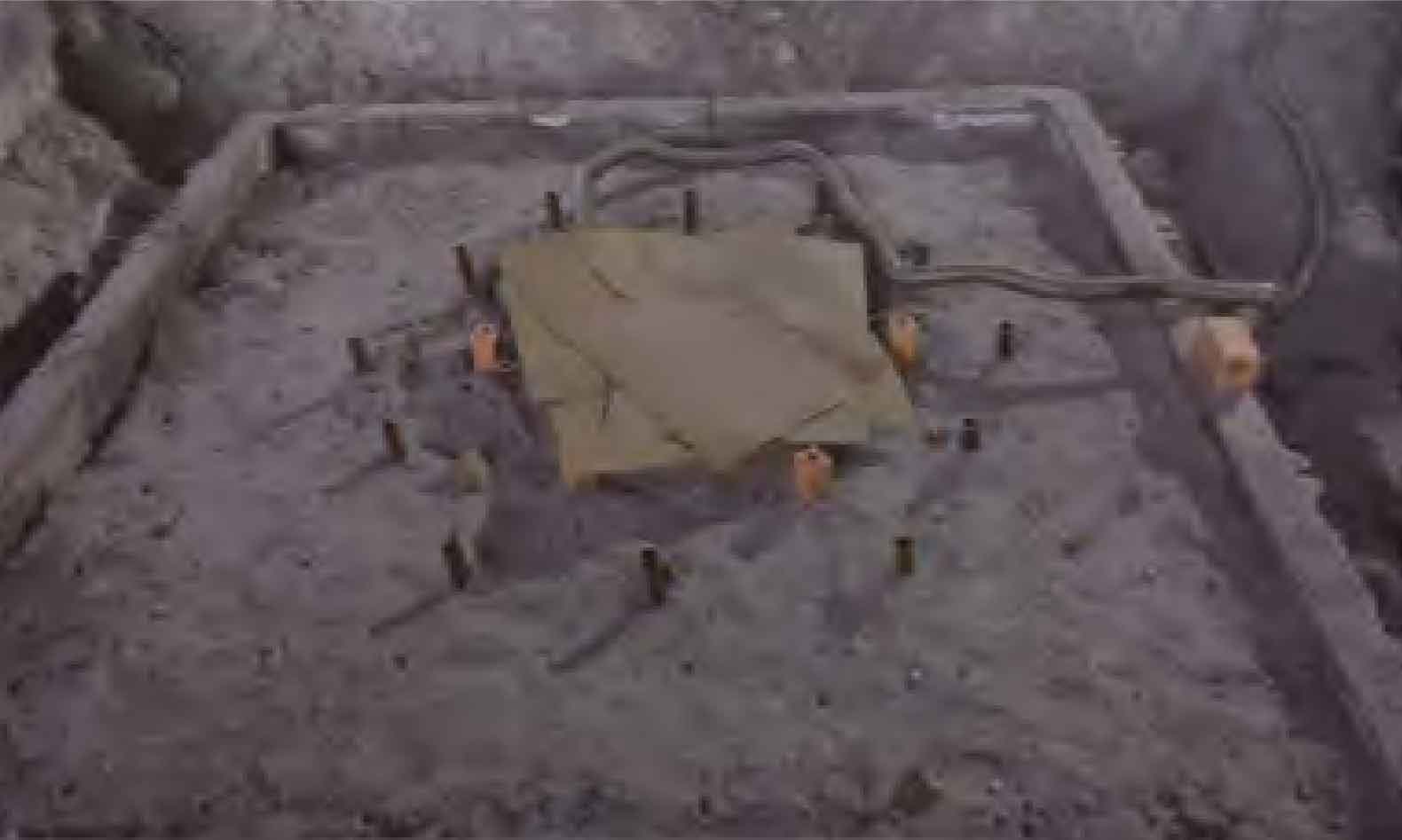
The air outlet at the outer wheel rim shall be arranged in the principle of fine diameter and multiple placement. Available ϕ The 25-35 mm steel pipe (widely sourced) is used as the air outlet. The air outlet is uniformly distributed along the circumference. The number of air outlets can be appropriate according to the circumferential distance between the two holes of about 400 mm, as shown in the figure.
