
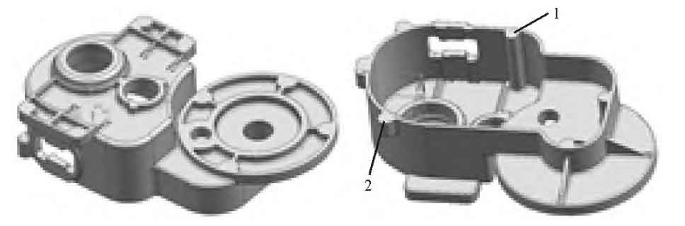
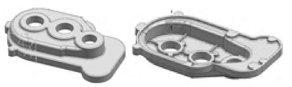
See Fig. 1 and Fig. 2 for the structure of box and cover. Sand castings are made of ZAlSi12 aluminum alloy, and the maximum outline size of the box is 307mm × 236.8mm × 90.5mm, the average wall thickness is 4mm, and the thickest part is 27mm; The maximum outline dimension of the box cover is 260mm × 167 mm × 39mm, the average wall thickness is 4mm, and the thickest part is 16mm. The thin wall area of the two sand castings is large, and most of the thickness is mainly distributed in the boss around the central hole and the position of the mounting screw, so these positions are prone to shrinkage cavity. The all metal mold casting process is adopted, and the mold steel is used for the appearance and core (with carbon nitrogen oxygen composite QPQ surface treatment).
1. Structural improvement of sand castings
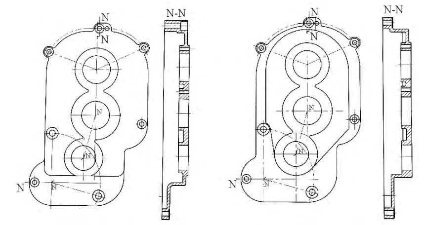
In order to increase the internal space of the gear box, the initial box cover structure was improved, as shown in Figure 3. Considering that the plane is too large, when the ejector pin structure is used to eject the box cover from the mold, the residual temperature of the sand casting is high, and the flat mold is very easy to deform. Moreover, the larger the plane of the sand casting is, the greater the degree of deformation is, and the greater the residual stress is, which leads to the addition of the correction process in the next process, and in serious cases, the sand casting is damaged by jacking. Therefore, in order to reduce the plane area, the noninterference position will be settled to reduce the plane size, and the position of the hole system will remain unchanged when the internal size is sufficient.
2. Feasibility of adopting all metal mold gravity casting process
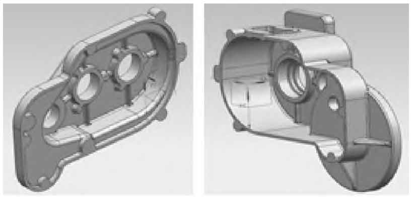
When sand casting is adopted, the two “ears” of the casting box (1 and 2 in Fig. 1) can only use movable block wood mold due to structural limitations in the molding process, which is prone to offset and warp during molding. When using metal mold casting, in order to reduce this defect, it is necessary to set up a core pulling mechanism with symmetrical distribution in the cavity below the ear. Therefore, the vertical casting process is adopted, as shown in Figure 4. The box cover is similar to the box structure with low height and similar process. For the consistency of process, similar pouring position and core pulling method are also used for the box.
3. Sand Casting Process Design
The all metal mold casting process of the box adopts bottom pouring, with left and right parting to ensure uniform mold filling. The sand casting process of the box is shown in Figure 5. The cavity in the middle of the box is deep, and the thickness of the boss is greater than the wall thickness of other parts. The molten liquid is required to form a temperature field that solidifies from bottom to top after entering the cavity. The number of risers can be increased. The boss that needs to be punched is cooled with copper rods (see Figure 5a). The core of the main cavity of the mold is air-cooled. The riser is set at the upper part, and the side bottom pouring method is used for pouring. The gate is set at the position with a boss outside, which is conducive to the forming of the boss contour. The pouring system is shown in Figure 5b.
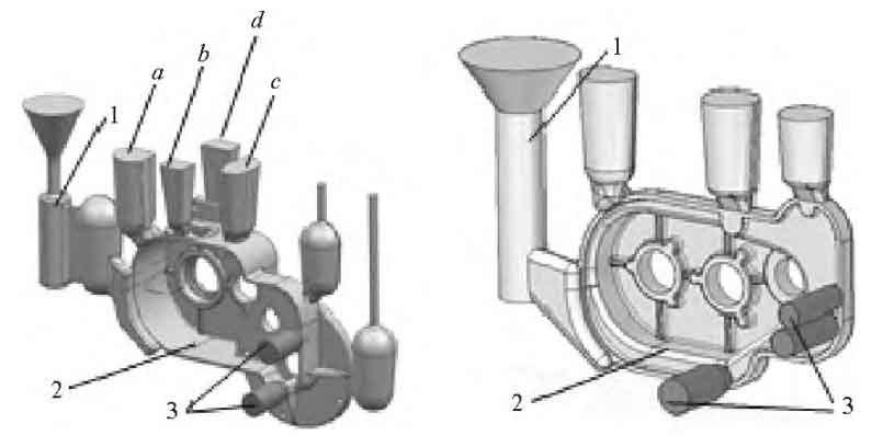
Gating and riser system 2. Casting 3. Red copper rod
According to the riser design theory of “shrink pipe method”, the main dimensions of box riser are calculated and designed, as shown in the table.
| Riser | Module of hot spot at feeding position | Riser pitch diameter/mm | Riser neck/mm | Riser neck modulus | Riser bottom / mm | Riser top / mm | Riser height/mm |
| a | 3.5 | 27.6 | 30X15 | 5.0 | Φ30 | Φ35 | 100 |
| b | 4.8 | 32.7 | 25X15 | 4.7 | 25X20 | 30X25 | 100 |
| c | 4.0 | 29.7 | 30X25 | 6.8 | 35X30 | 40X35 | 100 |
| d | 2.9 | 25.2 | 30X10 | 3.8 | 30X10 | 35X15 | 87.5 |
Wherein, the module of hot spot at the feeding position Mh is calculated according to the hot spot at the feeding position at the riser root; The shrinkage allowance is calculated based on the volume of the whole sand casting, and the shrinkage is 3%; Middle diameter of riser Dm = 2W + Dp; Thermal insulation wall thickness of riser W = 2Mh; Shrink tube diameter Dp = (2 /π · Vop) 1 / 3; The shrink pipe volume Vop is equal to the feeding amount evenly distributed to each riser; Riser height H = Hp + Hm; The pipe shrinking height Hp=2Dp, which shall be adjusted according to the mold structure required by the “homogenizing method”; The minimum pressure head Hm of riser is 20mm; The size of the bottom and top of the riser is calculated according to the riser taper, and the riser taper is about 0.3 °.