
1. Determination of casting process plan for BOP shell
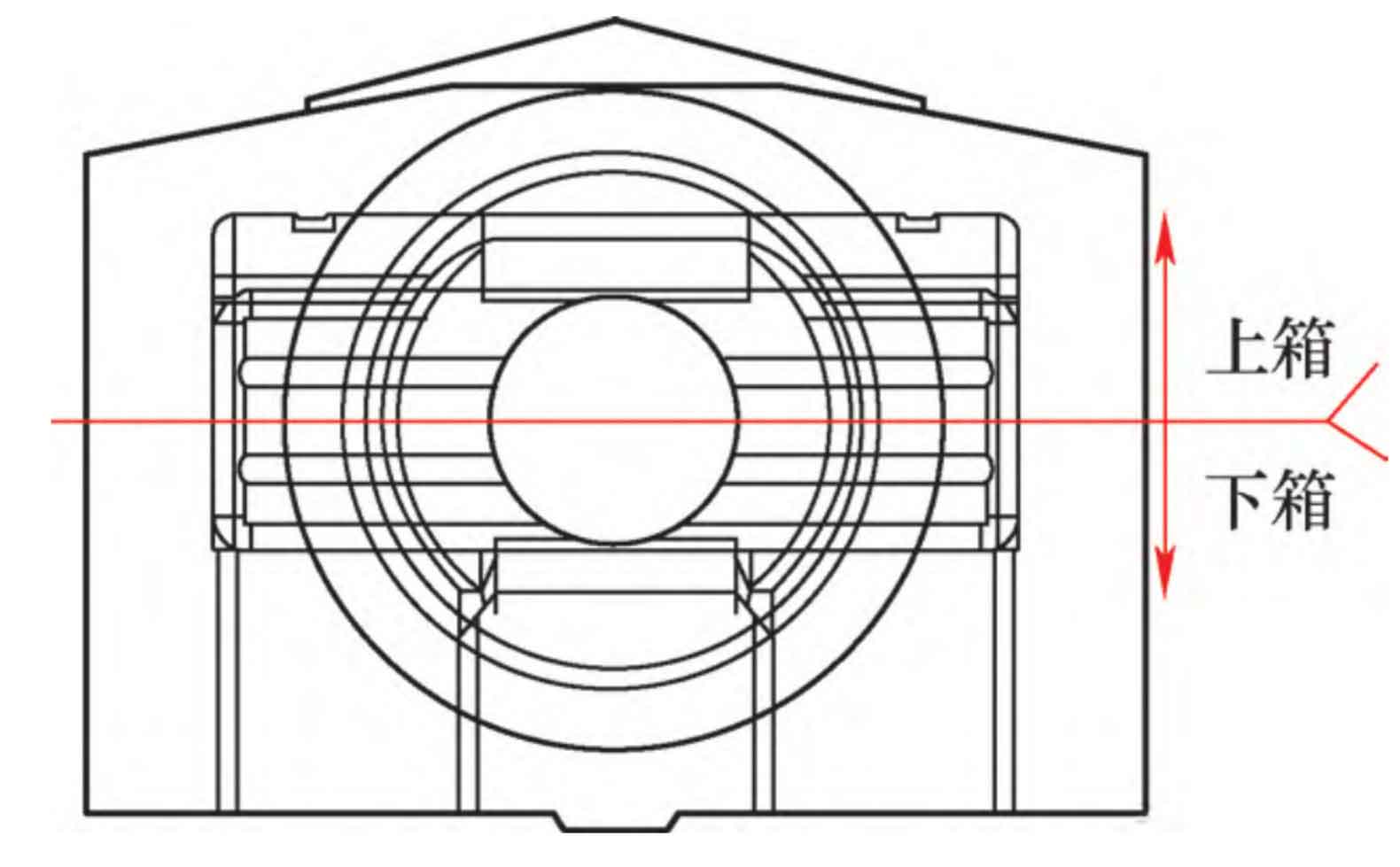
According to the solidification simulation analysis of the product digital model, combined with the structure of the BOP shell casting, considering the core and forming problems, the casting process plan of the BOP shell casting with the rectangular cavity downward is determined, as shown in Figure 1.
2. Design of BOP shell riser and cold iron
According to the product simulation analysis, the hot spots of the BOP shell casting are scattered, and many hot spots are formed at the conventional parts of the rectangular inner cavity and the transverse air passage. From the gradient, there are feeding islands. The wall thickness of the conventional hot spots reaches 350mm, and the riser is fed into the end area. Special cold iron is required to partition to ensure that the BOP shell casting does not produce shrinkage defects.
The riser modulus and hot spot modulus of BOP shell casting are calculated and designed by modulus calculation method. The basic principle of modulus method is that the riser should be delayed to solidify than the feeding part of the BOP shell casting, and the metal liquid in the riser should be used to feed the casting to make the casting compact.
The calculation formula of modulus method is:
Where, M – modulus of BOP shell casting (cm);
S – sectional area of BOP shell casting (cm2);
CL – excluding the section perimeter of non-radiating surface (cm).
Generally, the modulus relationship between the open riser and the BOP shell casting is M riser=1.2M pieces, and the modulus relationship between the blind riser and the BOP shell casting is M riser=1.4M pieces.
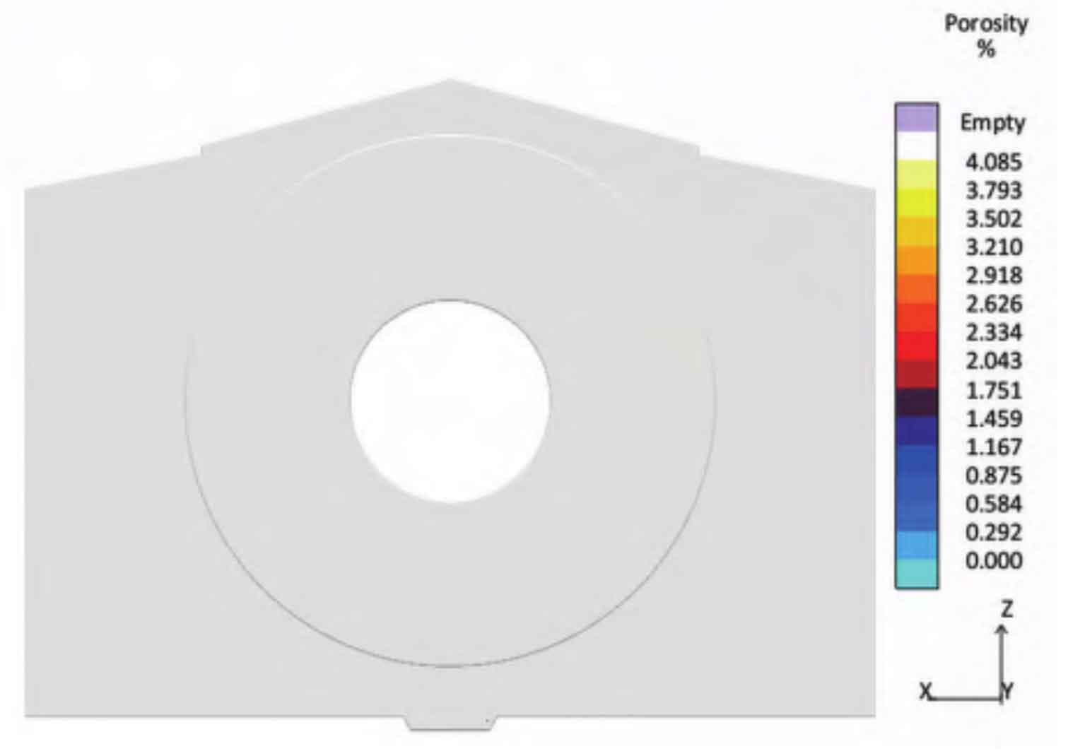
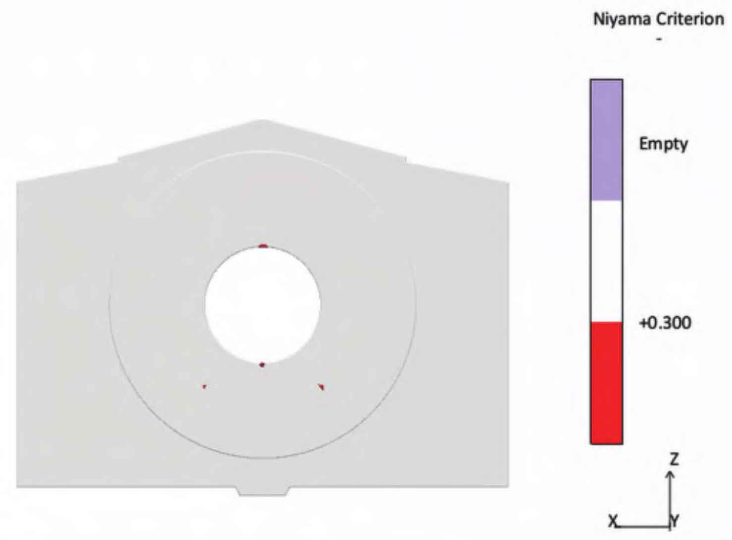
After the riser and chill are determined by modulus calculation, the MAGMA solidification simulation is applied to verify to ensure the sequential solidification and effective feeding, and to ensure that there are no excessive defects inside the blowout preventer. The simulation results of BOP solidification are shown in Figure 2.
3. Design of pouring system of BOP shell
The pouring system must ensure that the molten steel flows into the mold cavity smoothly, rapidly and continuously, and can exhaust and scum smoothly to prevent cracks, shrinkage and other defects caused by local overheating.
Considering the quality requirements of the blowout preventer, the pouring system is designed with a filter to prevent slag due to the small amount of molten steel poured. In order to reduce the hot spot at the end of the inner gate, duckbill gate is adopted. In order to prevent the slag in the molten steel from entering the mold cavity at the later stage of pouring, a supplementary pouring riser system is designed. The outflow speed of the inner gate shall be controlled below 1m/s. Using the simulation software MAGMA, the gating system was simulated and optimized.
4. Computer simulation and optimization of BOP shell casting process
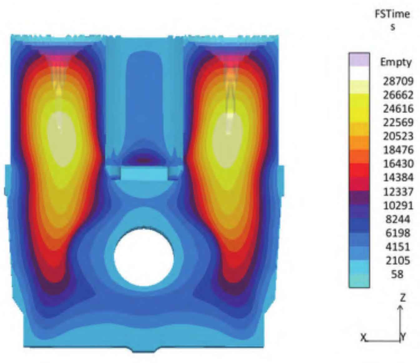
According to the MAGMA simulation analysis, the BOP shell casting has no excessive shrinkage porosity and central shrinkage hole. The safe distance of the riser of the BOP shell casting process meets the feeding requirements, the feeding gradient meets the sequential solidification requirements of the steel casting, the final solidification position is in the riser area, there is no isolated liquid phase zone in the BOP shell casting, and the cold iron zone between the risers is reasonable. The mold filling process is stable without splash and backflow. The average inlet velocity of each inner gate is less than 1m/s, and the mold filling temperature field distribution is conducive to casting solidification. The casting process simulation results of BOP shell are shown in Figure 3.
5. Determination of BOP shell modeling scheme
According to the structural characteristics and technical requirements of the BOP shell casting, combined with the hot spot simulation of the product and the consideration of the feeding gradient, the middle of the BOP flange is selected as the parting surface, and the inner cavity of the BOP shell casting is formed through core extraction to ensure the size of the inner cavity of the BOP shell casting.
The double-layer inner cavity has complex structure and small dimensional tolerance. If it is made into a single-layer sand core (see Fig. 4a), its length will reach 1975mm. The core box structure is complex, and the sand core is thin and easy to deform. Therefore, the double-layer inner cavity is designed as a double-layer sand core (see Fig. 4b); Due to the narrow inner cavity, the casting of the BOP shell is easy to adhere to sand, so the casting process of the BOP shell adopts special methods and coatings to ensure the surface strength of the sand mold and prevent sand adhesion. In addition, the core box must be made of solid wood to ensure the dimensional accuracy of the sand core.