40/70 mesh wood modified furan resin sand is used for manual molding, and the ratio of curing agent is 65wt.% Type A curing agent+35wt.% Type B curing agent, the amount of resin added is 1.0%~1.2%, and the amount of curing agent added is 30%~50% of the amount of resin.
1. Pouring time
According to the three-dimensional model analysis, the weight of the upper box nodular cast iron is 153 kg, and the weight of the molten iron is 215 kg; The weight of ductile iron castings in the lower box is 103 kg, and the weight of molten iron poured is 165 kg. The pouring time is determined according to the empirical formula of thin-walled parts with complex shape;
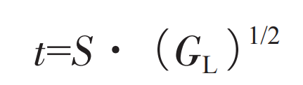
Where: t is pouring time (s); GL is the total weight of molten metal in the mold, including the weight of gating and riser system (kg); S is the coefficient, which is 1.2 according to the wall thickness of the main body of the casting and the material characteristics of ductile iron castings. It is calculated that the upper box t=16s and the lower box t=14s.
2. Size of gating system
Semi-closed gating system is adopted for the mold, with Σ A inner: Σ A transverse: Σ A straight=0.8 ∶ 1.3 ∶ 1.
The size of the gating system is determined by the design method of the flow resistance section, and the calculation formula is:
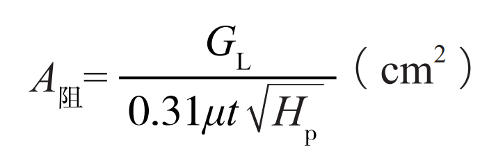
Where: resistance A is the minimum sectional area of the gating system (cm2); GL is the total weight of liquid metal flowing through the A-resistance section (kg); μ Is the flow loss coefficient, taken as 0.55; T is pouring time (s); Hp is the average static head height (mm). It is calculated that the upper box A resistance=17 cm2 and the lower box A resistance=15 cm2.
3. Casting process plan
The casting process scheme of ductile iron castings for the upper and lower boxes of the gearbox is shown in Figure 1-2. The dimensions of the upper box pouring system are: ∑ A inner=17 cm2, and the area of the three inner runners is 5.7 cm2; ∑ A transverse=28 cm2; Σ A straight=21.25 cm2, sprue diameter=52 mm; The pouring system dimensions of the lower box are: Σ A inner=15 cm2, and the area of the two inner runners is 7.5 cm2; Σ A A-transverse=24 cm2; Σ A straight=19 cm2, diameter=50 mm. For different parts of the box, risers and chills are set to control the solidification process of molten metal. The risers adopt Foxconn thermal insulation risers 7/10K and 5/8K, and the chills adopt gray cast iron or graphite chills. The thickness of the chills is 0.8~1.2 times of the wall thickness of the quenched ductile iron castings.
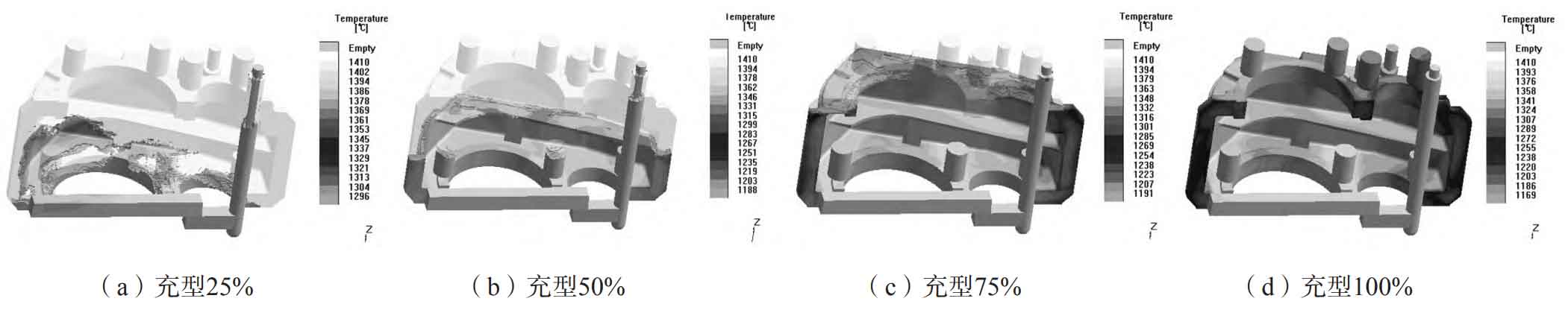
4. CAE analysis of flow field
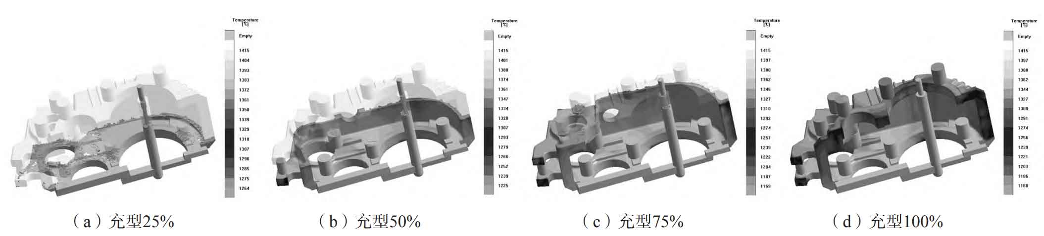
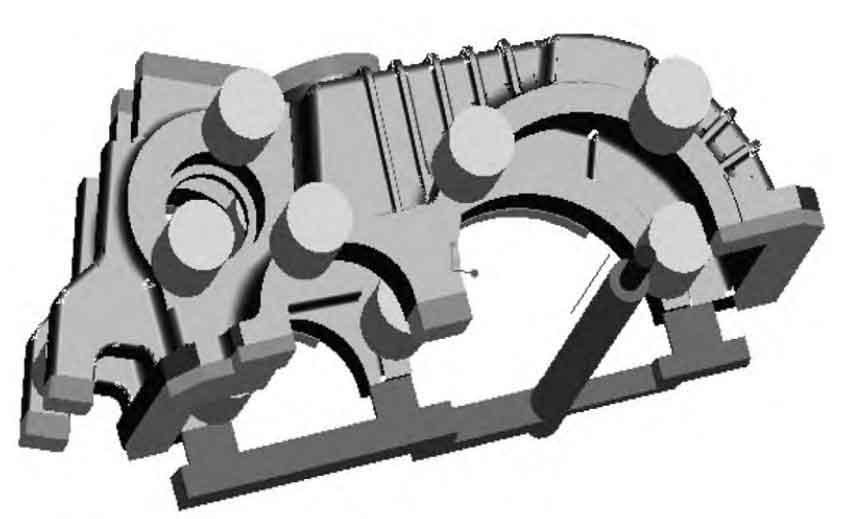
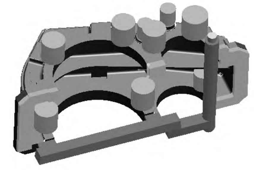
Figure 3-4 shows the simulation model of gear box ductile iron castings. Through Magma simulation analysis, the sprue adopts a small taper at the bottom and a large taper at the top. The molten iron quickly fills the bottom of the sprue, reducing the turbulence of molten iron in the sprue, so that there is no negative pressure zone in the sprue, avoiding the aspiration and oxygenation of molten iron, and enabling the slag to float on the upper surface of the sprue; The cross runner adopts large cross section, which slows down the flow speed of molten iron in the cross runner, reduces the turbulence and is conducive to the floating of slag; The thin and wide ingate is used, so that the liquid level in the transverse runner is fully higher than the top of the ingate, and then the ingate begins to fill. At this time, the slag will be higher than the ingate, so as to obtain a good slag blocking effect.
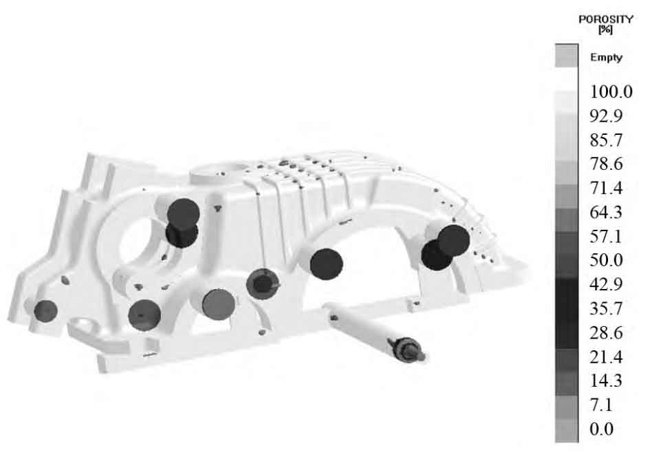
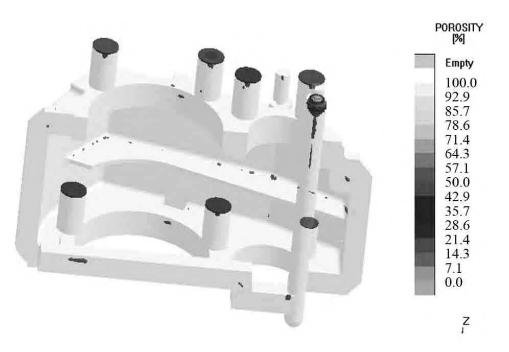
5. CAE analysis of solidification field
Figure 5-6 shows the CAE analysis of the solidification field of the gear box. Through the analysis of the distribution diagram of hot spots and shrinkage porosity of ductile iron castings, the riser and chill are set at different parts of the box to control the solidification process of liquid metal, so that the important parts of the box are free of shrinkage porosity defects and meet the quality requirements.