
A ductile iron developed and designed in this study for lost foam castingThe casting weight is 180kg, and its structural characteristics are local thick and twoThe total length of the oil passage is greater than 500mm.From the perspective of lost foam casting technology,Considering the fact that it is a paste-like solidification, ductile iron is prone to shrinkageDefects such as pores, shrinkage porosity, slag inclusion, etc. are simulated using the MAGMA simulation software.to simulate the pouring system scheme.Through process trial production,The problems of shrinkage cavity, slag inclusion, and defects in the machined end face were summarized and analyzed.
1. Process design
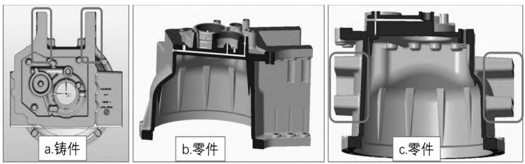
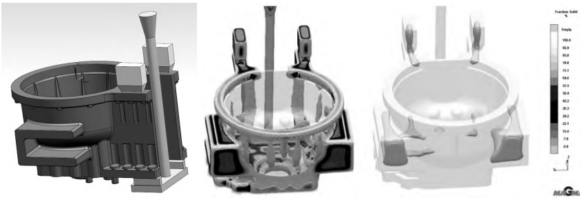
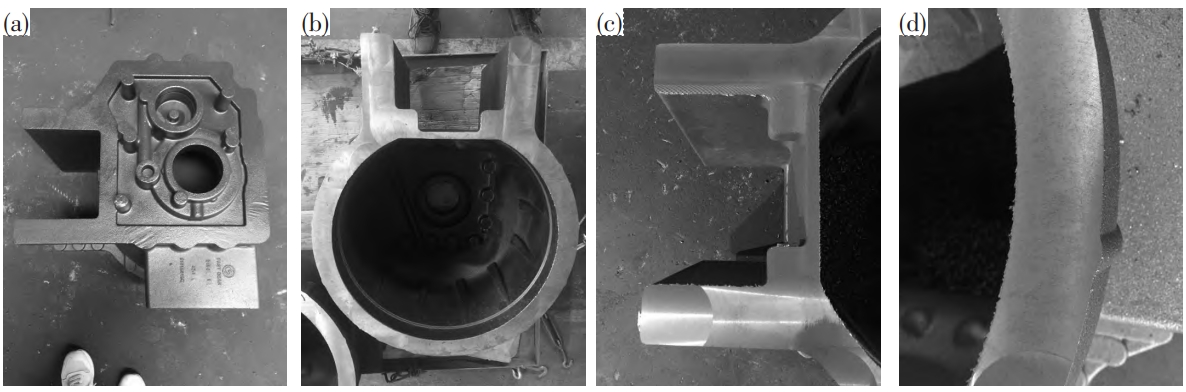
1.1 Structural analysisThe material of the ductile iron casting is QT400-15, and the outline dimensions of the casting are430mm × 620mm × 684mm, one piece per box, with a weight ofThe wall thickness of many parts of this casting is relatively thick, and the size of the marked area in Figure 1(a) is 183mm × 40mm × 59mm, which is prone to shrinkage.Figure 1(b) and Figure 1(c) are sectional views of the part, and there are two areas of the casting that requireTo process the oil passage, the total length is 510 mm, and the airtight leak detection pressure requirement is high.Defects are not allowed inside the oil passage.
1.2 Process plan and simulation
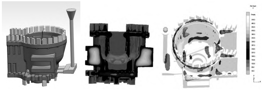
The gating system of ductile iron castings in lost foam casting is designedThe four schemes are: side bottom injection, top injection, stepped injection, and bottom injection.and using MAGMA simulation to compare the solidification and deformation of different solutions.The simulation results of the side bottom injection are shown in the figure. From the perspective of the solidification processAs the solidification time changes, the thinner areas solidify preferentially, and the thicker areasLarge-area solidification requires longer time.Parallel plates intersect with the upper end surfaceThe risk level of porosity in the region is high.Inside the ” U ” shaped boss on both sides of the castingThe bottom and boss may form a hot spot area, which also poses a risk of shrinkage.There is a high risk of shrinkage in dense areas.Time required for solidification processIt is positively correlated with the increase in wall thickness.Small slag collectors have a positive effect on the upper surface of the casting.The solidification process has little impact, and the effect of slag collection needs to be verified experimentally.The simulation results of top injection are shown in the figure, and the risk level of porosity is relatively high.The area is similar to the side bottom injection scheme.
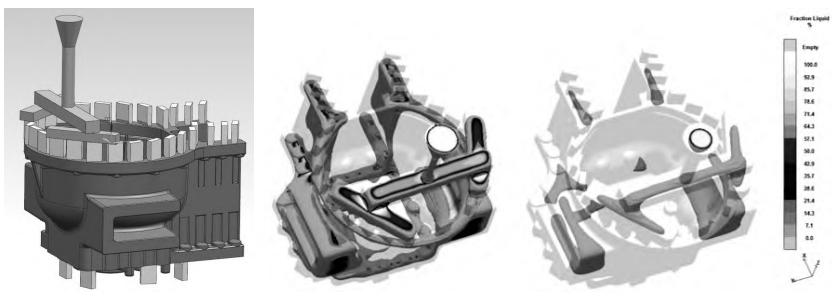
The simulation results of the stepped injection are shown in the figure, with the focus on the solidification process.The shrinkage risk area is concentrated in the inner part of the ” U ” shaped boss on both sides of the casting.The intersection area of the part, parallel plate, and upper end surface, and solidification at the inner gateAfter that, the upper end surface cannot be fed.
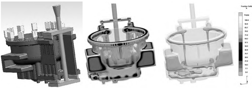
The simulation results of the bottom note are shown in the figure. During the solidification process, the upper endThe area of the hot spot is supplied by the feeder, but before the feeder is closed,There is shrinkage compensation, so the hot spot area on the upper end surface and the interior of the riser willForming porosity or shrinkage cavity, poor feeding effect, should be calculated and implemented throughCheck and make modifications.
1.3 Process experiment
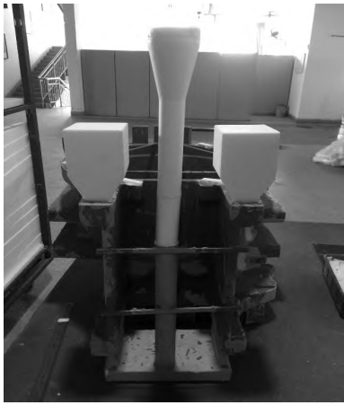
By analyzing the simulation results of MAGMA, we chooseProcess experiment was conducted by adding a riser and bottom injection system, as shown in the figure.
2 Defect analysis
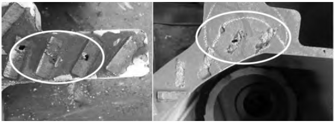
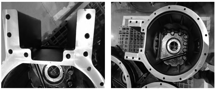
2.1 Major DefectsAs shown in the figure, there are shrinkage cavities on the upper end surface of the casting without a shrinkage feeder.The location is concentrated at the intersection of the parallel plate structure and the upper end surface.It is the main defect of ductile iron castings.
2.2 Causal analysis2.2.1 Analysis of the causes of shrinkage cavityAccording to the simulation results of MAGMA and the results of process experiments, the bridgeThe shell casting has shrinkage defects located on the upper end surface and two parallel platesThe intersection of thick and thin structures during solidification is more uniform than the surrounding areaThe thin-walled area solidifies slowly, and after the surrounding area solidifies, the thick-walled area inside solidifiesIf the process does not receive a supply of molten iron, it will form shrinkage defects such as porosity or shrinkage cavities.The solidification process of nodular cast iron is congealed [1], early stage of solidificationNo hard shell formation on the surface, with the precipitation of graphite, the pressure of eutectic expansionThis will lead to two phenomena: 1) the volume of liquid iron will increase, and with the passage of time,The length and solidification range are continuously expanding, and the final solidified area forms shrinkage cavities orPorosity, the volumetric shrinkage during the cooling process cannot change the already formed shrinkageDefects such as shrinkage or porosity may even increase the risk of shrinkage [2]2) expansion pressureThe force will directly act on the mold surface, causing the migration of the mold wall, swelling of the box,Poor phenomena such as shrinkage.Therefore, in order to avoid shrinkage porosity or shrinkage cavity defects in ductile iron castings,Two control measures are proposed: 1) appropriate shrinkage feeder,Shrinkage compensation in the section area [3]2) To enhance the rigidity of the mold, that is, to improve the sandThe compactness of the casting is maintained by continuous pressure for more than 15 minutes after the casting is completed.
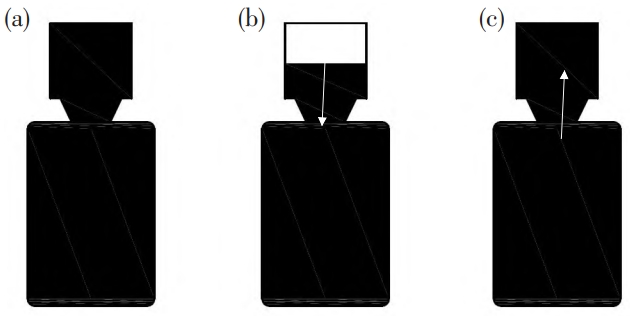
2.2.2 RiserIn this experiment, risers are divided into slag collecting risers and shrinkage filling risers based on their use.The main solution to shrinkage defects is to use a feeding riser, which is used to compensate forFill iron liquid and control pressure.Figure 8 shows three typical stages of pressure changes in the riser and moldParagraph [4]After the inner gate solidifies, no more molten iron enters the mold,At this time, the casting and the riser form a whole, as shown in Figure 8 (a);when the liquid metalWhen shrinkage occurs, the pressure in the mold interior riser is the highest at the ultimate state of shrinkage.Small, see Figure 8 (b);generated with the precipitation of graphite and the formation of austeniteexpansion, characterized by the expansion of liquid metal, which recharges the riserAs shown in Figure 8(c), with the continuous precipitation of graphite and austenite, the pressure inside the mold will increase, so the mold needs to have a certain degree of rigidity.When using lost foam casting ductile iron castings, the casting structure should be consideredSelecting the appropriate riser and the negative pressure of the sand box during the pouring process areIt cannot be ignored.
3. Improvement plan
Based on the above analysis, the choice of bottom casting for ductile iron castings in lost foam casting isThe pouring system of the injection and shrinkage risers was improved, and the parameters of the risers were also improved.
3.1 Improvement of risering parameters
The modulus of the hot spot area of the casting is MS, and the modulus of the riser is MR.The diameter modulus of the bushing is M N.Refer to the design principle of the traditional sand casting process riser, setTwo types of risers: 1# riser is MR=MS, MN=0.8MR;2# riser isMR = 1. 5MS 、MN = 0. 6MR。Except for the different riser sizes, the other controllable parameters are exactly the same.Conduct full-process trial production on two types of risers, and add anti-bumping, anti-impact,Improvement of deformation and pre-sand filling processes, verification of different risers on castingsThe improvement effect of shrinkage cavity at the hot spot position.
3.2 Improvement Effect
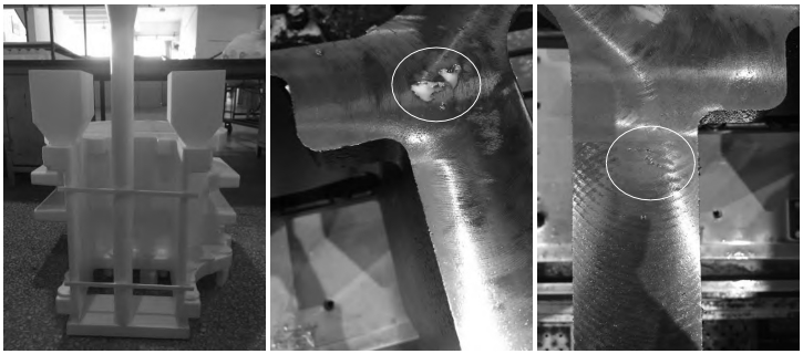
The lost foam casting selects the pouring system of bottom pouring and 1# riser,There is shrinkage cavity defect in the hot spot area after rough turning (the circle in the figureThe scrap rate reached 37%, as shown in the figure.
The pouring system of bottom pouring and 2# riser is selected for lost foam casting, which is roughThere is no obvious defect on the upper end surface of the casting behind the vehicle, as shown in Figure (b);there is no shrinkage porosity in the hot spot area, as shown in Figure (c);local observation reveals that there is a separation of the end surface.The small scattered defects are shown in Figure (d).After tracking and verification, the defects on the end face of the part were removed after the entire process, as shown in Figure.
4 Conclusion
1) The pouring process of ductile iron castings in lost foam casting selects bottom pouring.and match the dimensions of the lost foam casting riser, combined with the structure of the product.Conduct comparative experiments to obtain the best solution to shrinkage defects;2) After determining the pouring system for ductile iron castings in lost foam casting,It is also necessary to strengthen the whole process control, prevent collisions, and control the coating bakingDry, pouring negative pressure and pressure maintenance are beneficial to improving the quality of castings.Internal and external quality.