1. Introduction
In the field of modern manufacturing, the production of high-quality engine components is of paramount importance. The gantry cylinder block, with its unique structural characteristics, plays a crucial role in the performance and durability of engines. However, the casting process of gantry cylinder blocks is often plagued by various defects, which can significantly impact the quality and reliability of the final product. This article aims to provide a detailed and comprehensive analysis of the common casting defects encountered in gantry cylinder blocks and the corresponding effective solutions. By understanding these issues and implementing appropriate measures, manufacturers can enhance the casting quality, reduce production costs, and improve the overall performance of the engine.
2. Gantry Cylinder Block Structure and Casting Process Overview
2.1 Gantry Cylinder Block Structure
The gantry cylinder block is characterized by its specific design where the oil pan mounting plane is positioned below the crankshaft’s rotation center. This structural feature imparts enhanced strength and rigidity to the block, enabling it to withstand substantial mechanical loads. However, it also presents certain challenges in the casting process due to its relatively complex geometry and the need for precise dimensional control.
2.2 Casting Process
The casting process of gantry cylinder blocks typically involves several key steps, including pattern making, mold preparation, core making, melting and pouring of the metal, and finally, the solidification and cooling of the casting. Each of these steps requires careful attention to detail and strict adherence to process parameters to ensure the production of a defect-free casting.
3. Common Casting Defects and Their Causes
3.1 Cold Shut Defects
3.1.1 Appearance and Characteristics
Cold shut defects manifest as incomplete fusion of the molten metal during the filling process, resulting in the formation of either penetrating or non-penetrating gaps or cavities in the casting. The defect surface appears relatively smooth and often exhibits the shape of the initial flow of the molten metal.
3.1.2 Causes
- Pouring System Design: In the case of the 226B cylinder block, the original pouring system had the inner gate located too far from the upper plane. Additionally, the distribution of the upper plane’s gas outlets was disorganized due to the irregular positions of the bosses. This led to an uneven flow of molten metal, with the iron water converging in specific areas, such as between the second and third cylinders and the fourth and fifth cylinders. In regions like the fourth and fifth cylinders, where there was no sufficient iron water supply, cold shut defects were prone to occur.
- Casting Wall Thickness: The relatively thin wall thickness of certain parts of the casting, approximately 5.5 mm in the upper plane, caused rapid heat dissipation of the molten metal. As a result, the temperature of the iron water decreased rapidly, further exacerbating the likelihood of cold shut formation.
3.2 Gas Porosity Defects
3.2.1 Types and Formation Mechanisms
Gas porosity in cylinder blocks is commonly classified into three types: invasive gas porosity, precipitated gas porosity, and reaction gas porosity. In the case of the gantry cylinder block, invasive gas porosity is the predominant type, which occurs when gases generated by the sand core and molding sand become entrapped in the molten metal in the form of bubbles.
3.2.2 Causes
- Sand Core and Molding Sand: Residual moisture in the sand core and high moisture content in the molding sand can lead to significant gas evolution during the casting process. If the gas cannot escape effectively, it will be trapped in the molten metal, resulting in gas porosity.
- Pouring Temperature: An insufficient pouring temperature can cause the molten metal to solidify too quickly, preventing the gases from escaping. Conversely, an overly high pouring temperature may lead to increased oxidation of the metal, which can also contribute to gas porosity.
- Molding Sand Properties: The permeability of the molding sand is crucial. If the sand has low permeability, the gases generated during casting will have difficulty escaping, increasing the likelihood of gas porosity. Additionally, the type and amount of additives in the molding sand, such as bentonite, can affect its gas evolution characteristics.
- Core Quality and Assembly: Poor-quality sand cores, such as those with insufficient compaction or improper venting channels, can lead to gas entrapment. Inadequate clearance between sand cores during assembly can also block the gas escape paths, resulting in gas porosity.
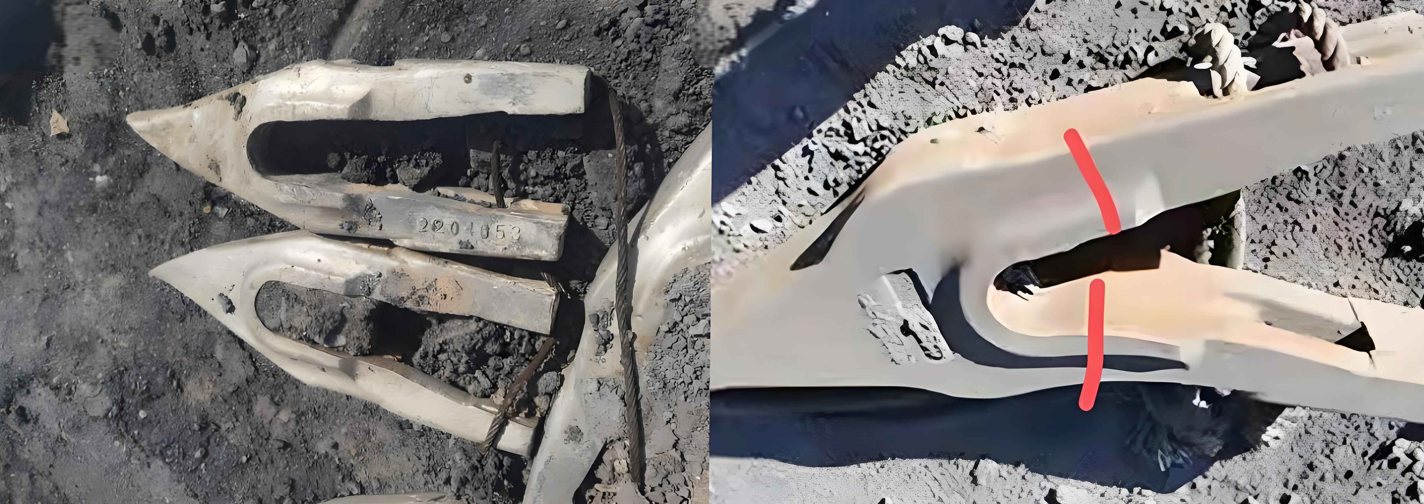
3.3 Damage Defects
3.3.1 Types and Occurrence Locations
Damage defects in gantry cylinder blocks can be categorized into two main types: those caused by human operation and those resulting from mechanical factors. These defects are more likely to occur in areas where the casting comes into contact with equipment and conveyor rollers during the cleaning and handling processes.
3.3.2 Causes
- Human Operation:
- Removal of Venting Risers: During the removal of venting risers, especially those located on slender bosses with gas pins, improper handling can cause damage to the bosses. If the damage affects the subsequent machining process, the casting may need to be scrapped, resulting in significant waste.
- Removal of In-gates: The previous location of the in-gate at the casting’s valve seat area could lead to coarse grain formation in the casting due to the high heat input. Moreover, improper removal of the in-gate could cause damage to the valve seat, affecting the casting’s quality and performance.
- Mechanical Factors: During the removal of the gating system and the shakeout process, the bosses on the lower side of the casting that come into contact with the equipment are prone to impact and cracking. This is mainly due to the relatively large size and weight of the gantry cylinder block, which makes it more susceptible to mechanical damage during handling.
4. Solutions to Casting Defects
4.1 Solutions for Cold Shut Defects
4.1.1 Pouring System Optimization
To address the cold shut defect, the pouring system was redesigned. As shown in Figure 3, an additional inner gate with a cross-section of 5 mm × 25 mm was added in the boxed area. Simultaneously, the inner gates at other valve seat positions were modified to 7 mm × 20 mm while maintaining the total cross-sectional area of the inner gates. This modification improved the rationality of the molten metal filling process, enhanced the fluidity of the iron water, and achieved a better diversion effect, thereby reducing the confluence of different inner gate iron waters on the large plane.
| Before Improvement | After Improvement |
|---|---|
| Inner gate far from upper plane, uneven gas outlet distribution | Additional inner gate added, optimized inner gate size and distribution |
| Iron water confluence in specific areas, prone to cold shut | Improved iron water flow, reduced cold shut occurrence |
4.1.2 Production Verification
After implementing the improved pouring system, production verification was carried out. The results showed that the cold shut defect was effectively resolved, and the porosity defect in the corresponding position was also significantly reduced. This demonstrated the effectiveness of the pouring system optimization in improving the casting quality.
4.2 Solutions for Gas Porosity Defects
4.2.1 Control of Sand Core and Molding Sand Quality
- Moisture Control: The moisture content of the sand core after exiting the drying kiln was strictly controlled to be below 0.6% before core setting and pouring. This measure effectively reduced the gas evolution from the sand core during casting.
- Molding Sand Moisture and Additive Adjustment: The moisture content of the molding sand was controlled below 2.9%. Additionally, the amount of bentonite added was reduced while ensuring the required strength of the molding sand, thereby improving its permeability.
4.2.2 Pouring Temperature Adjustment
The pouring temperature was increased from the original range of 1390 – 1400 °C to 1410 – 1420 °C. This increase in temperature improved the fluidity of the molten iron in the thin-walled areas and slowed down the formation of the oxide film on the surface of the molten metal, facilitating the escape of gases.
4.2.3 Core Quality and Assembly Improvement
- Core Quality Inspection: Stringent quality inspection of sand cores was implemented to ensure proper compaction and the integrity of venting channels. Cores with defects such as insufficient compaction or blocked venting channels were rejected.
- Clearance Optimization: The assembly clearance between sand cores was optimized to prevent the blockage of gas escape paths. This was achieved by carefully designing the core shapes and dimensions to ensure proper fit and gas flow.
4.2.4 Venting System Optimization
- Riser and Vent Pin Redesign: The layout and dimensions of the risers and vent pins on the upper plane of the casting were redesigned. Additional venting fins were added at the corresponding cylinder bore positions to enhance the gas escape from the sand core.
- Connection of Bosses for Venting: Irregular bosses were connected to nearby bosses with vent pins or directly integrated with them to improve the venting effect. For example, the bosses with inclined oil holes were connected to adjacent bosses to facilitate the escape of gases.
4.3 Solutions for Damage Defects
4.3.1 Prevention of Human-Induced Damage
- Riser and Vent Pin Design Improvement: To prevent damage during the removal of venting risers, the diameter difference between the bosses and the gas pins was increased, and a stepped structure was added between them. This design ensured that any fractures occurred at the interface between the boss and the stepped structure, preserving the machining allowance of the boss.
- In-gate Location Change: The location of the in-gate was changed from the valve seat area to the side wall above the valve seat. This modification reduced the heat input to the valve seat area during pouring, preventing coarse grain formation and minimizing the risk of damage during in-gate removal.
4.3.2 Reduction of Mechanical Damage
- Structural Strengthening: For bosses prone to impact and cracking, their diameters were increased or reinforcing ribs were added to enhance their structural strength. This modification reduced the likelihood of damage during handling and processing.
- Operation Standardization: Detailed operation standards were established for the casting cleaning process, and operators received targeted training. This ensured that the cleaning and handling operations were carried out in a standardized and careful manner, minimizing the occurrence of mechanical damage.
5. Conclusion
The casting of gantry cylinder blocks is a complex process that requires careful consideration of various factors to ensure the production of high-quality components. By understanding the common casting defects such as cold shut, gas porosity, and damage, and implementing the corresponding solutions, manufacturers can significantly improve the casting quality and reduce production costs. The optimization of the pouring system, control of raw material quality, and improvement of handling and cleaning processes are all essential steps in achieving defect-free castings. Continued research and development in casting technology will further enhance the performance and reliability of gantry cylinder blocks, contributing to the advancement of the automotive and machinery industries.