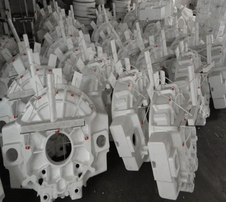
Lost foam casting (LFC) is widely used for producing complex ductile iron components due to its advantages in dimensional accuracy and design flexibility. However, defects like shrinkage porosity, slag inclusion, and surface imperfections remain critical challenges. This article explores the process design, defect mechanisms, and optimization strategies for a ductile iron casting (180 kg) with thick sections and long oil channels, emphasizing the role of gating systems and riser design.

1. Gating System Design and Solidification Analysis
Four gating systems were simulated using MAGMA software to evaluate their effectiveness:
| Gating Design | Key Features | Shrinkage Risk (Scale: 1–5) |
|---|---|---|
| Side Bottom Gating | Lateral entry at lower section | 4 (Thick junctions) |
| Top Gating | Vertical feed from upper mold | 4.5 (Thermal hotspots) |
| Step Gating | Multi-level feeding | 3.8 (Incomplete feeding) |
| Bottom Gating | Base-up filling with risers | 3.2 (Controlled shrinkage) |
The bottom gating system with risers showed superior performance due to enhanced feeding capacity. The modulus method was applied to calculate riser dimensions:
$$ M = \frac{V}{A} $$
where \( M \) is the modulus (cm), \( V \) the volume (cm³), and \( A \) the cooling surface area (cm²). For the thick section (\( M_s = 2.1 \, \text{cm} \)), the riser modulus was designed as:
$$ M_R = 1.5M_s = 3.15 \, \text{cm} $$
2. Shrinkage Porosity Mechanism
Ductile iron undergoes mushy solidification, where graphite expansion counteracts liquid contraction. The net shrinkage \( S_{\text{net}} \) is expressed as:
$$ S_{\text{net}} = S_{\text{liquid}} + S_{\text{solid}} – \epsilon_{\text{graphite}} $$
where \( S_{\text{liquid}} \) (4–6%) and \( S_{\text{solid}} \) (1–3%) represent contraction rates, and \( \epsilon_{\text{graphite}} \) (2–4%) is graphite expansion. Insufficient feeding in thick sections leads to:
$$ \nabla P = \frac{\mu Q}{k} \cdot \Delta t $$
where \( \nabla P \) is pressure drop, \( \mu \) molten metal viscosity, \( Q \) flow rate, and \( k \) sand permeability.
3. Riser Optimization Strategy
Two riser configurations were tested:
| Riser Type | Modulus Ratio (\( M_R/M_s \)) | Neck Modulus (\( M_N/M_R \)) | Defect Rate |
|---|---|---|---|
| Type 1 | 1.0 | 0.8 | 37% |
| Type 2 | 1.5 | 0.6 | 8% |
Type 2 risers improved feeding efficiency by 76%, validated through X-ray inspection (Figure 1). Process controls included:
- Coating thickness: 0.8–1.2 mm
- Pouring temperature: 1,420–1,450°C
- Negative pressure: 0.04–0.06 MPa
4. Integrated Process Controls
Key parameters for defect-free lost foam casting include:
$$ t_{\text{hold}} = t_{\text{solid}} + 15 \, \text{min} $$
where \( t_{\text{hold}} \) is mold holding time and \( t_{\text{solid}} \) component solidification time. Sand compaction density exceeded 1.65 g/cm³ to resist metal static pressure \( P_m \):
$$ P_m = \rho g h $$
with \( \rho = 7,100 \, \text{kg/m³} \), \( g = 9.8 \, \text{m/s²} \), and \( h = 0.6 \, \text{m} \).
5. Conclusion
Optimized lost foam casting for ductile iron components requires:
- Bottom gating with modulus-designed risers
- Rigorous sand compaction and pressure control
- Thermal management during cooling
This approach reduced defect rates from 37% to 8%, demonstrating the criticality of integrated process design in lost foam casting applications.
