
Lost foam casting (LFC) has revolutionized the production of complex castings like blast furnace cooling staves. This paper systematically analyzes critical process parameters including foam patterns, coating systems, and gating design to overcome common defects such as sand sticking and mold collapse. Through optimized production practices, we demonstrate how lost foam casting achieves higher efficiency and quality consistency compared to traditional resin sand casting.
1. Structural Characteristics of Cooling Staves
Cooling staves feature a plate structure with embedded cooling pipes, typically weighing 500-3,000 kg with wall thicknesses of 80-200 mm. Key performance requirements include:
| Parameter | Specification |
|---|---|
| Material | Ductile Iron (EN-GJS-400-18) |
| Working Temperature | 600-1,200°C |
| Cooling Water Pressure | 1.6 MPa (16 bar) |
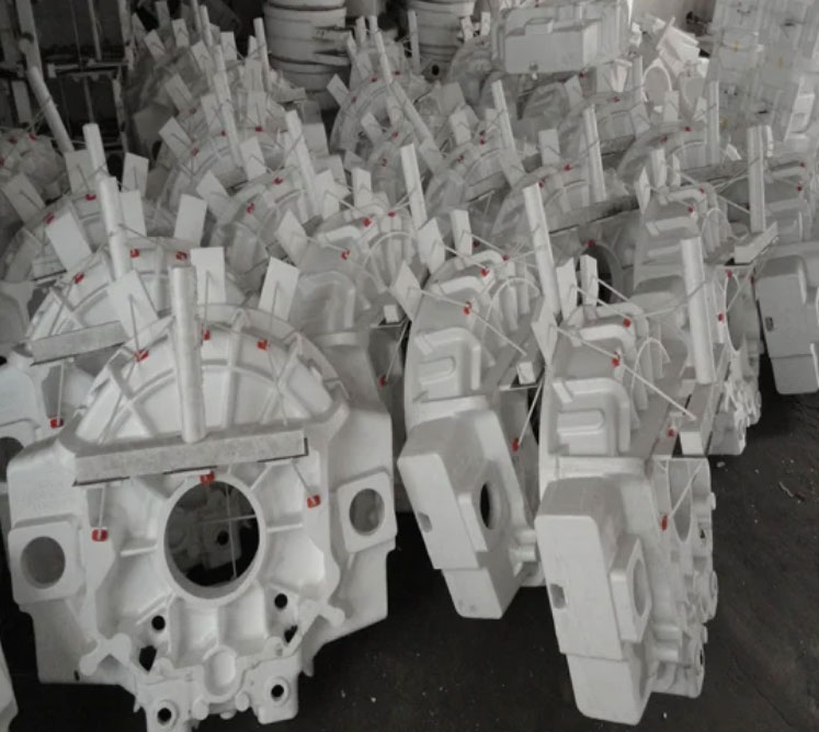
2. Foam Pattern Fabrication
The pattern quality directly affects casting dimensional accuracy. For cooling staves, we use:
$$ \text{EPS Density} = 16-18\ \text{g/L} $$
$$ \text{Pattern Shrinkage Allowance} = 2.1\% $$
| Density (g/L) | Strength | Gas Evolution |
|---|---|---|
| 16 | Moderate | 2.8 mL/g |
| 18 | High | 3.2 mL/g |
Multi-layer coating application parameters:
$$ \text{Coating Thickness} = \sum_{i=1}^{4} t_i = 1.0-1.5\ \text{mm} $$
Where \( t_i \) represents each coating layer thickness (0.25-0.4 mm per layer).
3. Cooling Pipe Integration
Seamless steel pipes (GB/T8163) require precise bending and anti-carburization treatment:
$$ \text{Bending Radius Tolerance} = \pm2\ \text{mm} $$
$$ \text{Wall Thinning Limit} = \frac{t_0 – t_f}{t_0} \times 100\% < 18\% $$
Anti-carburization coating specifications:
| Layer | Thickness (mm) | Composition |
|---|---|---|
| Base Coat | 0.1-0.15 | Al₂O₃ + SiO₂ |
| Top Coat | 0.05-0.1 | ZrO₂ + Binder |
4. Molding and Pouring Process
Gating system design for lost foam casting of large castings:
$$ Q = A \cdot v = \frac{m}{\rho \cdot t} $$
Where:
\( Q \) = Flow rate (m³/s)
\( A \) = Total choke area (m²)
\( v \) = Flow velocity (m/s)
\( m \) = Casting mass (kg)
\( \rho \) = Iron density (7,000 kg/m³)
\( t \) = Pouring time (s)
Optimal process window:
| Parameter | Value |
|---|---|
| Pouring Temperature | 1,320-1,380°C |
| Vacuum Level | -0.06 to -0.08 MPa |
| Solidification Time | 4-6 hours |
5. Quality Control Metrics
Post-casting inspection criteria:
$$ \text{Ball Pass Diameter} = 0.76D_{-0.2\ \text{mm}} $$
Where \( D \) = Pipe inner diameter
| Test | Standard | Acceptance |
|---|---|---|
| Hydrostatic | 1.6 MPa × 15 min | ≤3% pressure drop |
| Surface | Visual | No carbon defects |
6. Process Advantages
Lost foam casting demonstrates superior performance in cooling stave production:
$$ \text{Productivity Gain} = \frac{t_{\text{traditional}} – t_{\text{LFC}}}{t_{\text{traditional}}} \times 100\% > 35\% $$
Key benefits include:
– 40% reduction in machining allowance
– 25% lower scrap rate vs. sand casting
– 60% faster pattern preparation
This study confirms that lost foam casting technology effectively addresses the manufacturing challenges of large-scale metallurgical components while maintaining strict quality requirements. The combination of precise pattern control, advanced coating systems, and optimized pouring parameters establishes a reliable production framework for high-performance cooling staves.