
In the realm of advanced metal casting techniques, lost foam casting has emerged as a highly efficient method for producing complex components with superior surface quality, dimensional accuracy, and high process yield. This process is particularly advantageous for manufacturing ductile iron parts, such as gearbox housings, which demand exceptional mechanical properties including high strength, toughness, wear resistance, and vibration damping. However, during the production of these components using lost foam casting, defects like surface wrinkles and shrinkage cavities can arise, compromising the integrity and performance of the castings. In this study, we explore the underlying causes of these defects in ductile iron gearbox housings and present innovative solutions through process optimizations. Our focus is on enhancing the reliability and efficiency of lost foam casting by addressing specific challenges related to fluid dynamics and thermal management.
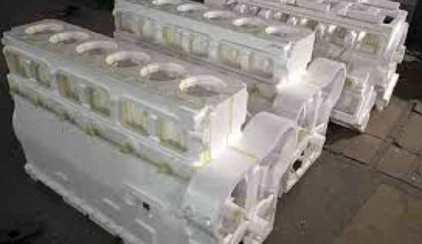
The gearbox housing under consideration weighs approximately 112 kg and features variable wall thicknesses, ranging from 14 mm to 54 mm, resulting in geometric hot spots that predispose the casting to shrinkage issues. Initially, the lost foam casting process for this component employed a top-gating system, which led to turbulent flow during pouring and subsequent surface wrinkles. Additionally, the concentration of thermal mass in certain regions caused shrinkage cavities, primarily in areas like bolt holes and thick sections. Through a detailed analysis, we identified that the root causes stem from inadequate gating design and insufficient heat dissipation in critical zones. By re-engineering the gating system to a bottom-gating approach and introducing a novel cooling fin technique, we successfully mitigated these defects. This article elaborates on our methodology, theoretical foundations, experimental validations, and the broader implications for lost foam casting applications.
Lost foam casting, also known as evaporative pattern casting, involves creating a foam pattern that is coated with a refractory material and embedded in unbonded sand. During pouring, the molten metal vaporizes the foam, replicating the pattern’s shape. This process offers significant benefits, such as reduced machining requirements and the ability to produce intricate geometries. However, it is susceptible to defects like wrinkles and shrinkage due to the decomposition by-products of the foam and the inherent solidification characteristics of the alloy. For ductile iron, which has a high carbon equivalent, these issues are exacerbated. Our investigation delves into the mechanisms of defect formation and proposes practical solutions that leverage the unique aspects of lost foam casting.
Wrinkle defects, often manifested as carbon folds or orange-peel-like surfaces, typically occur in regions where metal flow is sluggish or in “cold zones” of the casting. In lost foam casting, the foam pattern, usually made of copolymer materials to balance gas evolution and carbon content, decomposes upon contact with molten metal. This decomposition generates gaseous, liquid, and solid by-products. If these by-products are not efficiently evacuated from the mold cavity, they can accumulate and cause surface imperfections. For instance, in the original top-gating system, the molten iron entered from the top, leading to turbulent flow that created stagnant areas at the upper and side walls. This turbulence prevented the complete removal of decomposition residues, resulting in wrinkles. The mechanism can be described by the following relationship involving the flow velocity and pattern degradation:
$$ v = \frac{dm}{dt} \cdot \frac{1}{\rho A} $$
where \( v \) is the flow velocity, \( dm/dt \) is the rate of mass flow, \( \rho \) is the density of the molten metal, and \( A \) is the cross-sectional area. Turbulence increases the residence time of the metal in certain zones, allowing the by-products to interfere with the surface formation.
Shrinkage cavities, on the other hand, arise from volumetric contraction during solidification, particularly in hot spots where the local modulus is high. The modulus \( M \) is defined as the ratio of volume \( V \) to cooling surface area \( A \):
$$ M = \frac{V}{A} $$
In ductile iron, which has a carbon equivalent typically between 3.5% and 3.8%, the solidification process involves graphitization expansion, but this may not compensate fully in isolated thick sections. The original process did not adequately address these hot spots, leading to shrinkage defects in areas like bolt holes. Traditional solutions, such as risers or chills, are often impractical in lost foam casting due to complexities in pattern assembly and potential reductions in process yield. Therefore, we developed an alternative approach focused on enhancing heat dissipation through attached foam fins, which act as extended surfaces to promote directional solidification.
To quantify the issues, we analyzed the chemical composition and process parameters of the ductile iron gearbox housing. The table below summarizes the typical chemical composition required for QT450-10 grade ductile iron, which aligns with the material specifications used in our study:
| Element | Minimum | Maximum |
|---|---|---|
| C | 3.5 | 4.0 |
| Si | 2.0 | 3.0 |
| Mn | 0 | 0.45 |
| P | 0 | 0.05 |
| S | 0 | 0.025 |
| Mg | 0.02 | 0.06 |
| RE | 0.015 | 0.04 |
This composition ensures the mechanical properties meet the standards, but it does not prevent defects if the casting process is not optimized. The original process parameters included a pouring temperature of 1370–1440°C, a negative pressure of -0.06 to -0.04 MPa, and a holding time of 900 seconds. Despite these settings, defects persisted, indicating that the gating design and cooling strategies were inadequate.
For the wrinkle defect, our primary intervention involved redesigning the gating system from top-gating to bottom-gating. This change aimed to achieve laminar flow during mold filling, reducing turbulence and ensuring that the front-end metal, which carries impurities and decomposition by-products, is directed to non-critical areas like machining allowances. The theoretical basis for the gating design relies on fundamental fluid dynamics principles. The pouring time \( t \) can be estimated using the formula:
$$ t = k \cdot \sqrt[3]{W} $$
where \( k \) is a constant dependent on the casting geometry and material, and \( W \) is the weight of the casting. For our application, we used an empirical relationship derived from sand casting practices, adjusted for lost foam casting specifics. The average static pressure head \( H \) for bottom gating is calculated as:
$$ H = h – \frac{p}{2} $$
where \( h \) is the height of the sprue and \( p \) is the pressure loss due to friction. In our case, \( H \) was maintained at approximately 34 cm to ensure adequate flow without excessive velocity. The minimum cross-sectional area of the ingate \( A_{\text{min}} \) was determined using the equation:
$$ A_{\text{min}} = \frac{W}{\rho \cdot v \cdot t} $$
where \( \rho \) is the density of ductile iron (around 7.1 g/cm³), \( v \) is the flow velocity, and \( t \) is the pouring time. Based on calculations, \( A_{\text{min}} \) was found to be 3.46 cm². However, considering the unique requirements of lost foam casting, such as higher gas evolution and pattern decomposition, we increased the ingate area. The new design featured a central gating system with four ingates, each with dimensions of 7 mm × 40 mm, yielding a total area of 11.2 to 12.8 cm². This adjustment facilitated a more controlled filling process, as summarized in the table below:
| Parameter | Value |
|---|---|
| Pouring Time (s) | 24 (estimated) |
| Static Pressure Head (cm) | 34 |
| Minimum Ingate Area (cm²) | 3.46 |
| Actual Ingate Area (cm²) | 11.2–12.8 |
| Number of Ingates | 4 |
| Ingate Dimensions (mm) | 7 × 40 |
Experimental trials with this bottom-gating system demonstrated a complete elimination of surface wrinkles in over 2,000 production units. The laminar flow ensured that decomposition by-products were efficiently carried away, and the machining allowance at the top served as a reservoir for any residual contaminants. This outcome underscores the importance of gating design in lost foam casting for defect prevention.
For shrinkage cavities, we introduced a cooling fin technique, which involves attaching foam fins to the pattern at geometric hot spots. These fins increase the effective cooling surface area, thereby reducing the local modulus and enhancing heat dissipation. During the casting process, the negative pressure system draws ambient air through the sand mold, creating a convective cooling effect around the fins. The heat transfer can be modeled using the general equation for convection:
$$ q = h \cdot A \cdot \Delta T $$
where \( q \) is the heat flux, \( h \) is the heat transfer coefficient, \( A \) is the surface area, and \( \Delta T \) is the temperature difference between the casting and the environment. By increasing \( A \) through the fins, the heat flux \( q \) rises, accelerating solidification in critical zones. The modulus reduction can be expressed as:
$$ M_{\text{new}} = \frac{V}{A + A_{\text{fins}}} $$
where \( A_{\text{fins}} \) is the additional surface area from the fins. In our case, we attached 12 foam fins, each measuring 50 mm × 30 mm × 7 mm, to the bolt hole regions and other thick sections. The fins were integrated during the pattern assembly stage and underwent the standard coating, drying, and molding processes. The table below outlines the key aspects of this cooling fin technique:
| Parameter | Value |
|---|---|
| Number of Fins | 12 |
| Fin Dimensions (mm) | 50 × 30 × 7 |
| Material | Foam (Copolymer) |
| Attachment Method | Adhesive Bonding |
| Estimated Surface Area Increase (%) | Approximately 15–20 |
The implementation of this technique resulted in the elimination of shrinkage cavities in the bolt holes, as verified through machining and non-destructive testing. Over a batch of 2,000 castings, no defects were observed, confirming the efficacy of the cooling fins. This approach offers several advantages over traditional methods: it maintains a high process yield, simplifies post-processing, and avoids the complexities associated with risers or external chills. Moreover, it aligns well with the principles of lost foam casting, leveraging the existing negative pressure system for enhanced cooling.
In addition to the gating and cooling optimizations, we conducted a thorough analysis of the solidification behavior using thermal modeling. The rate of solidification \( R \) can be described by the Chvorinov’s rule:
$$ t = C \cdot \left( \frac{V}{A} \right)^n $$
where \( t \) is the solidification time, \( C \) is a constant, and \( n \) is an exponent typically around 2 for many casting alloys. By reducing the modulus \( M = V/A \) through the fins, the solidification time decreases, promoting a more sequential solidification pattern that minimizes shrinkage. Our experiments showed that the fins acted as artificial chill zones, creating temperature gradients that directed solidification from the fins toward the center of the hot spots.
Furthermore, we evaluated the impact of process parameters on defect formation. For instance, the negative pressure plays a crucial role in evacuating decomposition gases and enhancing cooling. The relationship between negative pressure and gas flow rate can be approximated by:
$$ Q = \frac{\Delta P \cdot A}{\mu} $$
where \( Q \) is the flow rate, \( \Delta P \) is the pressure difference, \( A \) is the cross-sectional area for flow, and \( \mu \) is the viscosity of the gas. By maintaining a negative pressure of -0.06 to -0.04 MPa, we ensured efficient removal of gases and adequate cooling through the sand and fins. This synergy between gating design and cooling strategies highlights the holistic approach required for optimizing lost foam casting processes.
The success of our interventions is evident in the consistent quality of the gearbox housings produced. The bottom-gating system not only resolved the wrinkle defects but also improved the overall filling stability, reducing the likelihood of other issues like misruns or cold shuts. The cooling fin technique, being innovative and low-cost, provides a scalable solution for similar components in lost foam casting. It is worth noting that the fins are consumed during the process, leaving no residual material on the casting, thus simplifying cleanup.
In conclusion, our study demonstrates that through systematic optimization of the gating system and the introduction of a cooling fin technique, we can effectively eliminate wrinkle and shrinkage defects in lost foam casting of ductile iron gearbox housings. The bottom-gating approach ensures laminar flow and proper venting of decomposition by-products, while the fins enhance heat dissipation in critical areas, reducing the local modulus and promoting directional solidification. These solutions not only improve casting quality but also uphold the advantages of lost foam casting, such as high process yield and design flexibility. Future work could explore the application of these techniques to other alloys and geometries, further advancing the capabilities of lost foam casting in industrial manufacturing.
The lost foam casting process, with its unique characteristics, continues to offer immense potential for producing high-integrity components. By addressing common defects through innovative engineering, we can unlock greater efficiencies and reliabilities in metal casting. Our findings contribute to the growing body of knowledge on lost foam casting and provide practical insights for foundries seeking to enhance their production processes. As the demand for complex and high-performance castings increases, such optimizations will play a pivotal role in meeting industry standards and customer expectations.