
In the field of metal materials, ductile iron has gained widespread use due to its excellent comprehensive properties, particularly in applications requiring high strength and ductility. The base structure of ductile iron is primarily ferritic, with typical grades such as QT450-10 being employed in industries like metallurgical machinery, petroleum chemistry, pipeline engineering, and transportation. However, as service environments for castings become more demanding, the performance requirements for ductile iron have increased significantly. Compared to mixed-matrix ferritic ductile iron, silicon-solid-solution-strengthened ferritic ductile iron offers superior strength, toughness, and machinability. This has led to growing research interest in high-silicon ferritic ductile iron. The lost foam casting process, which involves the vaporization of foam patterns during pouring, presents unique challenges, such as heat dissipation affecting pouring temperature control. Improper temperatures can lead to defects like non-metallic inclusions or reduced spheroidization efficiency. Moreover, silicon content influences the eutectic temperature of ductile iron, thereby impacting the matrix microstructure. Thus, investigating the production of fully ferritic high-silicon ductile iron via lost foam casting is of great importance. In this study, we examine the effects of silicon content ranging from 2.9% to 4.6% on the microstructure and mechanical properties of high-silicon ductile iron produced through lost foam casting, analyzing the underlying mechanisms of silicon’s role.
The lost foam casting process distinguishes itself from traditional sand casting by utilizing foam patterns that gasify during pouring, which removes heat and necessitates precise control over pouring temperature. If the temperature is too low, non-metallic inclusions may form, while excessive temperatures can impair spheroidization and promote carbide formation, degrading performance. Silicon content also affects the eutectic temperature, influencing the matrix structure. Therefore, achieving a fully ferritic matrix in high-silicon ductile iron through lost foam casting is a critical research objective. We prepared high-silicon ductile iron samples with silicon contents of 2.9% to 4.6% using lost foam casting under specific conditions: a pouring temperature of 1,487°C, a negative pressure of 0.05 MPa, and a nodulizer addition of 1.3%. The chemical composition was designed to maintain a constant carbon equivalent, calculated as:
$$ \omega(CE)\% = \omega(C)\% + 0.3[\omega(Si)\% + \omega(P)\%] $$
where $\omega(CE)$ represents the carbon equivalent, and $\omega(C)$, $\omega(Si)$, and $\omega(P)$ denote the mass fractions of carbon, silicon, and phosphorus, respectively. This approach ensured that variations in silicon content were balanced by adjustments in carbon content to keep the carbon equivalent stable. The samples were cast into Y-block patterns with a wall thickness of 24 mm, following the standard GB/T 1348-2019. The chemical compositions of the four sample groups are summarized in Table 1.
| Sample ID | C | Si | Mn | P | S | Mg | Residual RE | CE |
|---|---|---|---|---|---|---|---|---|
| A | 3.52 | 2.92 | 0.183 | 0.029 | 0.0058 | 0.064 | 0.0160 | 4.4 |
| B | 3.09 | 3.68 | 0.273 | 0.027 | 0.0057 | 0.068 | 0.0155 | 4.2 |
| C | 2.88 | 4.22 | 0.311 | 0.026 | 0.0037 | 0.059 | 0.0155 | 4.15 |
| D | 2.60 | 4.59 | 0.265 | 0.024 | 0.0046 | 0.057 | 0.0145 | 3.98 |
For microstructural analysis, the as-cast samples were machined into 10 mm × 10 mm × 10 mm specimens, ground, polished, and etched with a 4% nitric alcohol solution for 10–15 seconds. Observations were conducted using optical microscopy (OM) and scanning electron microscopy (SEM). Image analysis software was employed to quantify the relative content and size of ferrite and graphite, in accordance with the standard GB/T 9441-2021. Mechanical properties were evaluated using a universal tensile testing machine for tensile tests and a digital Brinell hardness tester for hardness measurements. The tensile specimens had a parallel section diameter of 14 mm, a gauge length of 70 mm, and an overall length of 180 mm.
The microstructure of the ductile iron samples revealed that all specimens exhibited a fully ferritic matrix, regardless of silicon content. The graphite morphology consisted of spheroidal graphite with a spheroidization rate exceeding 90%, and the roundness remained largely unchanged. As silicon content increased, the graphite particles became finer and more uniformly distributed. Quantitative analysis of graphite characteristics is presented in Table 2.
| Sample ID | ω(Si) (%) | Graphite Count (per mm²) | Graphite Diameter (μm) |
|---|---|---|---|
| A | 2.92 | 151 | 35.6 |
| B | 3.68 | 165 | 30.8 |
| C | 4.22 | 208 | 27.7 |
| D | 4.59 | 223 | 26.0 |
The ferrite matrix also showed refinement with increasing silicon content. The average ferrite grain size decreased, as detailed in Table 3. This refinement is attributed to the elevated eutectic temperature caused by higher silicon levels, which increases the undercooling at the solidification front and enhances the nucleation rate of ferrite.
| Sample ID | ω(Si) (%) | Ferrite Content (%) | Ferrite Grain Size (μm) |
|---|---|---|---|
| A | 2.92 | 88.8 | 43.77 |
| B | 3.68 | 89.9 | 42.06 |
| C | 4.22 | 90.0 | 38.63 |
| D | 4.59 | 91.7 | 35.38 |
The mechanical properties of the ductile iron samples were significantly influenced by silicon content. Tensile strength, yield strength, elongation, and hardness were measured, and the results are compiled in Table 4. As silicon content increased, both strength and hardness improved, while elongation remained relatively stable. This indicates that high-silicon ductile iron produced via lost foam casting achieves a favorable balance of strength and ductility.
| Sample ID | ω(Si) (%) | Tensile Strength (MPa) | Yield Strength (MPa) | Yield Ratio | Elongation (%) | Hardness (HBW) |
|---|---|---|---|---|---|---|
| A | 2.92 | 441 | 325 | 0.737 | 17.0 | 128.0 |
| B | 3.68 | 527 | 425 | 0.806 | 18.0 | 149.0 |
| C | 4.22 | 601 | 512 | 0.852 | 17.0 | 174.6 |
| D | 4.59 | 683 | 588 | 0.861 | 17.5 | 186.1 |
Fracture surface analysis using SEM revealed that lower silicon contents (e.g., 2.92%) resulted in ductile fracture characterized by dimples centered on graphite particles. As silicon content increased to 4.59%, the fracture mode shifted towards brittle characteristics, with cleavage facets and intergranular fracture observed. However, the overall macroscopic plasticity remained acceptable due to the fine and uniform graphite distribution in the fully ferritic matrix.
The mechanism behind silicon’s effect on high-silicon ductile iron involves solid solution strengthening, grain refinement, and lattice distortion. Silicon dissolves in ferrite to form a substitutional solid solution, as the atomic radius of silicon (0.118 nm) is smaller than that of iron (0.121 nm) but larger than the interstitial sites in ferrite (approximately 0.0766 nm). The Fe-Si phase diagram indicates that within the silicon range of 2.9% to 4.6%, only the ferrite phase exists, with silicon fully soluble. The microhardness of ferrite increased with silicon content, as shown in Table 5, confirming the solid solution strengthening effect.
| Sample ID | ω(Si) (%) | Ferrite Microhardness (HV) | Average Microhardness (HV) |
|---|---|---|---|
| A | 2.92 | 180.88, 187.47, 188.17, 187.48, 186.79 | 186.16 |
| B | 3.68 | 230.59, 223.68, 211.63, 222.72, 227.58 | 223.24 |
| C | 4.22 | 237.59, 244.34, 230.51, 229.08, 249.87 | 238.28 |
| D | 4.59 | 244.62, 245.65, 266.16, 259.36, 249.78 | 253.17 |
Energy-dispersive spectroscopy (EDS) analysis was performed at grain boundaries and within grains to assess silicon segregation. The segregation index $K_{Si}$ was calculated as:
$$ K_{Si} = \frac{w_{Si}}{w_{Si0}} $$
where $w_{Si}$ is the silicon content at the measurement point, and $w_{Si0}$ is the average silicon content in the ductile iron. Results indicated that at lower silicon contents (2.92%), silicon segregated within grains, whereas at higher contents (4.59%), segregation occurred predominantly at grain boundaries. This increased segregation at grain boundaries exacerbates lattice distortion, enhancing strength but reducing plasticity. The lattice parameter of ferrite was calculated using X-ray diffraction (XRD) data. For body-centered cubic (BCC) ferrite, the interplanar spacing $d$ for planes (hkl) is given by:
$$ d = \frac{a}{\sqrt{h^2 + k^2 + l^2}} $$
where $a$ is the lattice constant. The calculated lattice constants for different silicon contents are listed in Table 6. As silicon content increased, the lattice constant decreased, indicating greater lattice distortion. The distortion degree was computed relative to pure iron (lattice constant 0.28664 nm), showing an increase from 0.06% to 0.22% with rising silicon content.
| ω(Si) (%) | a (110) (nm) | a (200) (nm) | a (211) (nm) | Average a (nm) | Distortion Degree (%) |
|---|---|---|---|---|---|
| 2.92 | 0.28628 | 0.28655 | 0.28659 | 0.28647 | 0.06 |
| 3.68 | 0.28642 | 0.28612 | 0.28620 | 0.28625 | 0.14 |
| 4.22 | 0.28607 | 0.28638 | 0.28608 | 0.28618 | 0.16 |
| 4.59 | 0.28606 | 0.28600 | 0.28600 | 0.28602 | 0.22 |
In summary, the lost foam casting process effectively produces high-silicon ductile iron with a fully ferritic matrix. The increase in silicon content refines both graphite and ferrite grains, enhancing strength and hardness through solid solution strengthening and grain refinement. Silicon dissolution in ferrite causes lattice distortion and segregation, which further contribute to the mechanical properties. The optimal silicon content of 4.59% results in a tensile strength of 683 MPa, hardness of 186.1 HBW, and elongation of 17.5%, demonstrating excellent comprehensive performance. This research provides a theoretical foundation for applying lost foam casting to large-scale high-silicon ductile iron components, emphasizing the critical role of process control in achieving desired microstructures and properties.
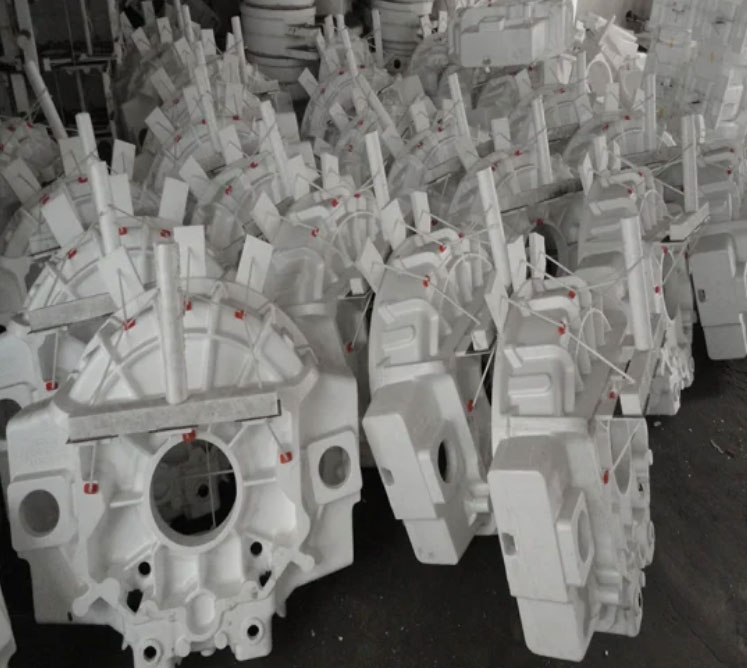
The lost foam casting technique, as illustrated, involves complex interactions between pattern vaporization and metal solidification, which must be carefully managed to avoid defects. In our experiments, maintaining a pouring temperature of 1,487°C and negative pressure of 0.05 MPa ensured proper mold filling and minimized inclusions. The use of lost foam casting allows for precise replication of complex geometries, making it suitable for industrial applications such as automotive and machinery parts. Future work could explore the effects of other alloying elements or process parameters on high-silicon ductile iron produced via lost foam casting, further optimizing its performance for demanding environments.