
In the field of heavy-duty engineering vehicles, axle shells play a critical role in transmitting power and bearing substantial loads. These components must exhibit high strength, toughness, fatigue resistance, and weldability to withstand harsh operating conditions, such as those found in mining environments. Traditional manufacturing methods like sand casting and V-process casting have been commonly used, but the emergence of lost foam casting has offered a promising alternative. However, producing high-quality cast steel axle shells using lost foam casting has been challenging due to issues like carbon pick-up, cracking, inclusion-related leakage, and deformation. This article delves into our first-hand experience in addressing these challenges through innovative process modifications, material selections, and operational techniques in lost foam casting.
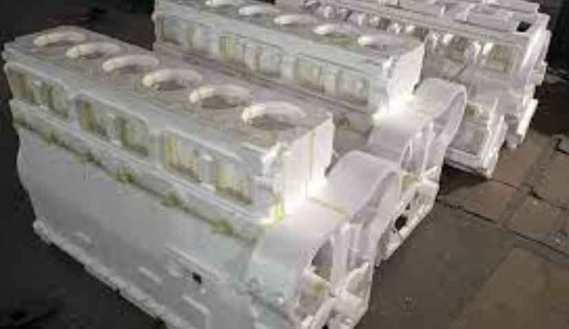
Lost foam casting involves creating a foam pattern that is vaporized upon contact with molten metal, leaving behind a precise casting. For heavy-duty axle shells, which feature complex geometries with varying wall thicknesses (e.g., thin sections of 12–16 mm and thicker flanges of 35–60 mm), this process must be meticulously controlled. Our initial attempts with lost foam casting revealed significant drawbacks: uneven carbon pick-up from the foam degradation, stress-induced cracks at transition zones, inclusions leading to oil leakage in sealed cavities, and distortions during drying and cooling phases. These issues often resulted in components that failed to meet rigorous standards, such as pressure testing at 0.3–0.5 MPa for over 10 minutes and magnetic particle inspection post-heat treatment. To overcome these, we focused on optimizing every aspect of the lost foam casting process, from pattern making to pouring, emphasizing the use of advanced materials like STMMA beads and implementing techniques such as empty cavity pouring and high-frequency vibration.
The core of our approach in lost foam casting revolved around selecting the right foam material. We compared expanded polystyrene (EPS) and STMMA beads, noting that STMMA, with a lower carbon content of 69.6% compared to EPS’s 92%, significantly reduces the risk of surface carbon pick-up in low-carbon steel castings. Although EPMMA beads (60% carbon) would be ideal for minimal carbon residue, their high cost made STMMA the practical choice for large-scale production in lost foam casting. The foam patterns were produced using a one-piece molding technique to avoid seams that could lead to defects, with a controlled density of 20–23 g/cm³ to enhance structural integrity and minimize deformation during handling. After forming, patterns were dried naturally for 4–6 hours on specially designed supports to maintain dimensional accuracy, a critical step in the lost foam casting process to prevent warping.
Coating application is another vital element in lost foam casting, as it provides the necessary strength, refractoriness, and gas permeability. We developed a proprietary coating formulation to address the unique demands of axle shells: sodium bentonite (3 parts), CMC (3 parts),木质纤维素 (0.5 parts), xanthan gum (0.5 parts), water-soluble polyethylene alcohol (0.5 parts), 85% bauxite (200 mesh, 80 parts), and 99% quartz powder (200 mesh, 20 parts), with water adjusted for different coating layers. This mixture ensured excellent adherence and minimal dripping, with a coating thickness of 3–4 mm on internal surfaces and 2.0–2.5 mm externally. Such thicknesses balanced gas evolution control and mold rigidity, crucial for preventing collapse in the lost foam casting process. During drying, we used custom frames to support the patterns, reducing deformation risks—a common pitfall in lost foam casting for elongated components like axle shells.
In terms of process design, we experimented with two main gating and risering configurations in lost foam casting. The first involved center pouring with risers at both ends to feed the isolated hot spots, such as the flange and spring mounting areas. However, this led to a 20% collapse rate due to inadequate support in the cavity. The second design positioned the shell horizontally with a tilted riser and pouring at one end, which reduced collapse to 5%. Further improvements included adding a steel tube (Ø26 mm) inside the cavity as a reinforcement, effectively eliminating collapses in the optimized lost foam casting setup. Additionally, we incorporated anti-cracking rings (8 mm × 25 mm) at the flange transitions to mitigate stress concentrations, a common source of cracks in lost foam casting. The gating system was designed to facilitate rapid filling under vacuum, with calculations for pouring parameters derived from empirical data. For instance, the pouring temperature was maintained between 1,600 and 1,620°C, and the vacuum pressure was controlled at 0.05–0.06 MPa during foam burning, dropping to 0.03–0.04 MPa after cavity evacuation. The relationship between vacuum pressure and filling velocity can be approximated as: $$v = \frac{P_{\text{vacuum}} \cdot A}{\mu \cdot \rho}$$ where \(v\) is the filling velocity, \(P_{\text{vacuum}}\) is the vacuum pressure, \(A\) is the cross-sectional area, \(\mu\) is the viscosity, and \(\rho\) is the density of the molten steel. This equation highlights how lost foam casting relies on vacuum to draw metal into the mold, unlike conventional methods.
Melting and pouring practices were refined to enhance the quality of lost foam casting. We used scrap steel with low carbon (<0.2%) and low phosphorus/sulfur (<0.025%) contents, melted in medium-frequency furnaces. Deoxidation was performed in the furnace with silicon-aluminum-barium and in the ladle with pure aluminum, ensuring a total aluminum content of 0.04–0.08% to improve fluidity and reduce oxides. To minimize inclusions—a persistent issue in lost foam casting due to the inability of slag to float—we employed bottom-pour ladles coupled with argon shielding during pouring. This combination reduced oxidation and ensured cleaner metal entry. The pouring time was kept under 10 minutes per ladle to maintain thermal consistency, a key factor in lost foam casting for preventing premature solidification in thin sections.
A critical innovation in our lost foam casting process was the implementation of empty cavity pouring, where the foam pattern is completely burned out before metal introduction. This involved using oxygen torches to ignite and consume the STMMA foam, monitored until flames extinguished in all risers, indicating full evacuation. This step minimized carbon pick-up and prevented gas-related defects like blows or misruns. The carbon pick-up can be modeled as: $$\Delta C = k \cdot C_f \cdot t$$ where \(\Delta C\) is the increase in carbon content, \(C_f\) is the carbon content of the foam, \(t\) is the exposure time, and \(k\) is a process-dependent constant. For STMMA, this resulted in a negligible carbon increase, whereas EPS could lead to increments of 0.2–0.4%. After pouring, high-frequency vibration was applied from the moment metal entered the risers until vacuum release (60–120 seconds post-pour). This vibration refined the grain structure by disrupting dendrite formation, as described by the equation for grain size reduction: $$d = \frac{K}{\sqrt{f}}$$ where \(d\) is the average grain diameter, \(K\) is a material constant, and \(f\) is the vibration frequency. This contributed to improved mechanical properties in the final lost foam casting.
To validate our lost foam casting approach, we conducted multiple trials and evaluated the axle shells for mechanical performance and integrity. The chemical composition and mechanical properties are summarized in the tables below, demonstrating compliance with stringent standards. For example, the tensile strength and impact absorption met or exceeded requirements, with no shrinkage defects detected in critical sections. Pressure testing confirmed leak-proof performance, affirming the effectiveness of our lost foam casting modifications.
| Element | Composition (wt%) |
|---|---|
| C | 0.20–0.25 |
| Si | 0.3–0.5 |
| Mn | 1.1–1.4 |
| Cr | 0.20–0.35 |
| Mo | 0.15–0.25 |
| S, P | ≤0.025 |
| Al | 0.4–0.8 |
| V, Ni, Cu | ≤0.03 |
| Property | Value |
|---|---|
| Tensile Strength (MPa) | 600–680 |
| Yield Strength (MPa) | 420–500 |
| Elongation (%) | ≥18 |
| Reduction of Area (%) | ≥36 |
| Impact Absorption (J/cm²) | ≥35 |
| Hardness (HB) | 190–240 |
Despite these successes, deformation remained a challenge in approximately 20% of castings, primarily due to uneven cooling stresses in the lost foam casting process. This necessitated post-heat treatment pressing to achieve dimensional tolerances. However, the overall quality, as assessed through microstructure analysis and fatigue testing, confirmed that our lost foam casting method produced components capable of withstanding full load conditions without failure. The refined grains from vibration, combined with the empty cavity technique, resulted in a homogeneous microstructure with enhanced toughness.
In conclusion, our extensive work in lost foam casting for heavy-duty engineering axle shells has demonstrated that through careful material selection, process optimization, and innovative techniques, it is possible to overcome common defects. The use of STMMA beads, empty cavity pouring, anti-cracking rings, bottom-pour ladles with argon shielding, and high-frequency vibration collectively contributed to producing high-integrity castings. Lost foam casting, when executed with precision, offers a viable and efficient manufacturing route for complex steel components, though ongoing efforts are needed to further reduce deformation and enhance cost-effectiveness. This experience underscores the importance of a holistic approach in lost foam casting, where every step—from pattern making to pouring—must be aligned with the component’s specific requirements to achieve optimal results.