
In the field of casting manufacturing, the lost foam casting process has emerged as a highly efficient and cost-effective method, particularly for producing large, thin-walled shell components. As an engineer specializing in casting processes, I have been involved in the development of a lost foam casting technique for a tractor transmission case, which presented significant challenges due to its complex geometry, substantial size, and minimal wall thickness. The primary objective was to design a robust process that minimizes defects such as deformation, cold shuts, and sand adhesion, while leveraging the economic advantages of lost foam casting over traditional sand casting methods. Through systematic analysis, numerical simulation, and experimental validation, we successfully optimized the process, achieving controlled deformation and high-quality castings.
The transmission case under consideration is made of HT250 gray iron, with a theoretical weight of 265.1 kg and overall dimensions of 816 mm × 530 mm × 578 mm. The wall thickness varies significantly, ranging from approximately 14 mm to 50 mm, which amplifies the risk of deformation during the lost foam casting process. Deformation control is critical, as it can arise from multiple stages, including pattern assembly, sand filling, and pouring. Additionally, cold shuts and sand burn-on are common issues that require precise management of process parameters. To address these challenges, we conducted a thorough analysis of the component’s structure and designed multiple casting schemes, evaluating them through numerical simulations to identify the most viable approach.
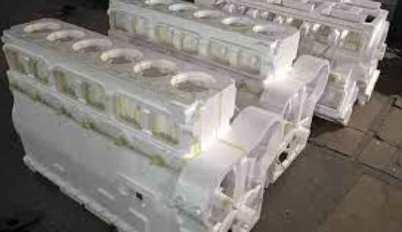
In the initial phase, we focused on mold design, employing a split-type scheme along the central plane to divide the pattern into two sections. This facilitated the production of high-quality foam patterns with consistent dimensions. The mold was constructed using GBZL106 material, with surface treatments to ensure smoothness and durability. Critical parameters, such as bead pre-expansion density and molding conditions, were strictly controlled to produce patterns that met dimensional tolerances. For instance, the pre-expansion density was maintained at (25 ± 1) g/L, and cooling water temperature was kept below 40°C during pattern formation. The resulting foam patterns exhibited minimal defects, such as shrinkage or distortion, as confirmed by dimensional inspections summarized in the table below.
| Measurement Point | 3D Model Dimension (mm) | Theoretical Pattern Dimension (mm) | Actual Pattern Dimension (mm) |
|---|---|---|---|
| Width 1 | 390 | 394.3 | 394.1 |
| Width 2 | 530 | 536.4 | 536.3 |
| Width 3 | 365 | 369.4 | 369.6 |
| Length 1 | 578 | 584.9 | 585.2 |
| Width 4 | 40 | 40.5 | 40.7 |
| Minimum Wall Thickness | 14 | 14.2 | 14.6 |
| Height | 816 | 825.8 | 825.5 |
| Length 2 | 486 | 491.8 | 491.8 |
| Side Lug | 54.4 | 55.1 | 55.2 |
| Width 5 | 485 | 490.8 | 490.8 |
| Partition Thickness | 27 | 27.4 | 27.6 |
Three distinct lost foam casting process schemes were conceptualized and subjected to numerical simulation using a dedicated casting simulation system. Scheme 1 involved a flat placement with top gating, utilizing a sprue diameter of 50 mm, runner cross-section of 40 mm × 20 mm, and ingate cross-section of 40 mm × 7.5 mm, with a pouring head of 210 mm. Simulation results indicated potential defects like slag entrapment and shrinkage porosity in specific regions, necessitating the addition of overflow structures. Moreover, the flat orientation increased the risk of mold collapse during sand filling and pouring, requiring meticulous control of sand compaction and pouring speed.
Scheme 2 employed an inclined placement with side gating, featuring a sprue diameter of 50 mm, runner cross-section of 60 mm × 55 mm, ingate cross-section of 55 mm × 15 mm, and a pouring head of 190 mm. This configuration demonstrated reduced tendencies for slag and shrinkage defects, as the inclined position facilitated better sand compaction and minimized turbulence during metal filling. However, it introduced complexities in sand filling and vibration, demanding multiple sand additions and low-amplitude, high-frequency compaction. The simulation outputs for this scheme showed a more favorable temperature gradient during solidification, lowering the risk of defects.
Scheme 3 adopted a vertical placement with top gating, with a sprue diameter of 50 mm, runner cross-section of 45 mm × 50 mm, ingate cross-section of 60 mm × 15 mm, and a pouring head of 320 mm. While this allowed for two castings per mold box, enhancing productivity, the simulation revealed disordered filling patterns that could lead to cold shuts and inclusions. Additionally, sand filling in vertical orientations proved challenging, often requiring pre-filled self-hardening sand in certain areas to ensure proper compaction.
Based on the simulation outcomes and practical considerations of our production line, we selected Scheme 2 as the baseline and implemented optimizations to enhance its performance. The optimized design included additional ingates to increase the filling velocity and reduce temperature gradients during solidification. The modified gating system parameters were as follows: sprue diameter remained at 50 mm, runner cross-section was adjusted to 60 mm × 55 mm, and multiple ingates with cross-sections of 55 mm × 15 mm were incorporated. Numerical simulations of the optimized scheme confirmed improved filling characteristics, with a more uniform temperature distribution and minimized risk of shrinkage porosity. The solidification process can be modeled using the Chvorinov’s rule, expressed as:
$$ t = C \left( \frac{V}{A} \right)^n $$
where \( t \) is the solidification time, \( V \) is the volume of the casting, \( A \) is the surface area, \( C \) is a constant dependent on the mold material, and \( n \) is an exponent typically around 2 for sand molds. In lost foam casting, this relationship helps in predicting solidification behavior and optimizing the process parameters to avoid defects.
The experimental phase involved meticulous pattern assembly, coating application, and molding. Patterns were assembled in a one-piece-per-mold configuration, with gating systems designed to ensure smooth metal flow. Coating was applied via dipping, with specific Baume degrees for each layer: 69–71 for the first coat, 67–69 for the second, and 65–67 for the third. The coated patterns were dried in a controlled environment at 40–55°C for over 12 hours, with mass changes limited to 5 g to confirm dryness. The molding process utilized a sand filling technique with a base sand thickness of 100 mm and face sand thickness of 30 mm. Pouring was conducted at temperatures between 1,490°C and 1,510°C, under a vacuum pressure of 5.5–6 MPa, with a designed pouring time of 90 seconds per mold and a holding time exceeding 20 minutes.
Post-casting, the components underwent shot blasting, revealing surfaces free of significant defects. Hardness measurements ranged from HB180 to HB190, consistent with material specifications. To assess deformation, 3D scanning was performed on the cast blanks, and the resulting models were compared against the theoretical CAD data. The comparison showed minimal deviations, confirming that the lost foam casting process effectively controlled deformation within acceptable limits. Furthermore, machining trials demonstrated that the castings met all dimensional and quality requirements, with no observed defects such as cold shuts or sand inclusions.
The success of this lost foam casting development underscores the importance of integrated process design and simulation. By leveraging numerical modeling, we could preemptively identify potential issues and refine the gating and placement strategies. The economic benefits of lost foam casting for large thin-walled parts are substantial, as it reduces material waste, energy consumption, and tooling costs compared to conventional sand casting. For instance, the dry sand recovery rate in lost foam casting exceeds 95%, significantly lowering environmental impact and operational expenses. The cost savings can be quantified using the formula:
$$ C_{savings} = (C_{sand} – C_{lost foam}) \times W $$
where \( C_{savings} \) is the total cost reduction, \( C_{sand} \) and \( C_{lost foam} \) are the per-ton costs of sand casting and lost foam casting, respectively, and \( W \) is the weight of the casting. In this case, the savings amounted to approximately $1,000 per ton for large thin-walled components.
In conclusion, the development of this lost foam casting process for large thin-walled shell parts demonstrates the viability of the technique in overcoming challenges like deformation and defect formation. Through systematic design, simulation, and experimentation, we achieved a optimized process that ensures high-quality castings with minimal resource expenditure. The insights gained from this project can be extended to other complex components, further advancing the application of lost foam casting in industrial manufacturing.