
In my years of industrial practice, the lost foam casting process has proven to be a transformative technology for producing high-integrity metal parts. From its development decades ago to its current mature state, it offers a compelling alternative to traditional sand casting. Specifically, for the batch production of railroad track components such as rail braces, joint fishplates, limiters, sole plates, gauge plates, spacer blocks, and washers, the advantages are pronounced. This process delivers castings with dimensional stability and superior surface finish. Its streamlined workflow, which allows for precise net-shape forming without machining allowances, combined with a typical surface roughness achievable of 12.5µm, meets stringent application requirements directly. A fully enclosed lost foam casting production line facilitates cleaner, high-volume manufacturing while significantly improving the working environment. The quality of the final product in lost foam casting is predominantly governed by equipment selection and meticulous process control. This detailed account, from my first-person perspective, will delve into the critical stages—from bead pre-expansion to heat treatment—ensuring the final product conforms to all technical specifications. I will incorporate tables and formulas to summarize key parameters and relationships inherent to a robust lost foam casting process.
The foundation of a successful lost foam casting process is laid at the very first step: pre-expansion. We employ fully automatic, steam-based batch pre-expanders. These machines feature automated feeding, PLC control, and touch-screen operation. For railroad components with wall thicknesses ranging from 15 to 40 mm, achieving uniform bead expansion is paramount. The target is to minimize the pre-expansion density without compromising the foam pattern’s formability and subsequent strength. Our equipment offers an expansion ratio range of 30-60, with a controlled density error of ±1 kg/m³. The pre-expansion density ($\rho_{pre}$) is a critical parameter derived from the initial bead density ($\rho_0$) and the volumetric expansion ratio ($R_v$):
$$
\rho_{pre} = \frac{\rho_0}{R_v}
$$
Controlling steam pressure, temperature, and exposure time is essential to achieve a consistent, closed-cell foam structure with the target density.
| Process Parameter | Target/Control Range | Influence on Bead Quality |
|---|---|---|
| Steam Pressure | 0.8 – 1.2 bar | Drives expansion; too high causes bead collapse. |
| Steam Temperature | 105 – 115 °C | Provides heat for polymer softening. |
| Cycle Time | 30-120 seconds (adjustable) | Determines final bead size and density. |
| Target Pre-Expansion Density | 18 – 28 kg/m³ (product-dependent) | Affects pattern surface finish, strength, and gas evolution during casting. |
The next critical phase is pattern molding. We utilize semi-automatic hydraulic molding presses. The platen size is selected to accommodate various molds. The process involves manual pressurized feeding of pre-expanded beads into the aluminum alloy (GBZL104 equivalent) mold, followed by PLC-controlled cycling. Mold design is entrusted to experienced manufacturers. Key considerations include a mold body wall thickness of 12-15mm for strength and thermal uniformity, an outer steam jacket wall of 18-20mm with reinforcing ribs, and secure module alignment using dowel pins. Critical surfaces are coated with a TEFLON release agent. Accounting for polymer and metal shrinkage is vital; we apply a differential shrinkage ratio ($k_{shrink}$) to the mold cavity dimensions ($D_{mold}$) based on the casting’s geometry to achieve the desired final casting dimension ($D_{casting}$) after all contractions:
$$
D_{mold} = D_{casting} \times (1 + k_{shrink})
$$
The molding cycle consists of: mold preheating & shot filling, steam injection for secondary expansion/fusion, water spray cooling, and demolding. The steam pressure and time must be optimized to ensure complete bead fusion without defects like under-filling or burning. A properly molded pattern is smooth, rigid, and possesses sufficient compressive strength.
| Molding Defect | Likely Cause | Corrective Action |
|---|---|---|
| Poor Bead Fusion | Insufficient steam time/temp; Low bead density | Increase steam cycle; Adjust pre-expansion density. |
| Swirl Marks / Blisters | Condensate in mold; Excessive steam | Ensure proper mold drainage and venting; Reduce steam time. |
| Pattern Collapse | Inadequate cooling; Premature demolding | Increase cooling time/coolant flow. |
| Non-Fill | Low feed pressure; Bead bridging | Adjust feed pressure; Modify gate design. |
Following demolding, every pattern requires trimming. The parting line flash must be meticulously removed to maintain surface quality. For components like washers and rail braces, the contact faces with the rail are critically inspected and finished to ensure flawless assembly. This manual step prevents costly post-casting grinding.
Coating application is arguably one of the most crucial steps in the lost foam casting process. We use a paint muller for preparation and a low-speed agitated dip tank for application. The coating must balance rheological properties (suspension, brushability, non-drip) with functional requirements (strength, permeability, refractoriness, insulating capability, crack resistance). The coating thickness ($t_{coat}$) is a vital compromise governed by a relationship involving sand grain size ($d_{sand}$) and a safety factor ($S_f$):
$$
t_{coat} \propto S_f \cdot d_{sand}
$$
A coating that is too thin leads to metal penetration (burn-on), while one that is too thick impedes degassing, causing porosity. The prepared slurry is mixed for over 4 hours to achieve homogeneity. During dipping, the pattern’s orientation and motion are controlled to ensure a uniform, drip-free layer. Complex assemblies require strategic hanging points to avoid pooling.
| Coating Property | Test Method | Target Value | Purpose |
|---|---|---|---|
| Density (Baumé) | Hydrometer | 65 – 75 °Bé | Controls slurry consistency and coat weight. |
| Viscosity (Ford Cup #4) | Flow Cup | 35 – 50 seconds | Ensures proper dip coverage and drainage. |
| Permeability | Specialized Tester | High (Product-Specific) | Allows pyrolysis gases to escape during pour. |
| Layer Thickness (dry) | Thickness Gauge | 0.5 – 1.2 mm | Barrier against sand; must remain permeable. |
Drying the applied coating requires precise control. We use a temperature-and humidity-regulated drying chamber equipped with exhaust fans. The initial drying temperature must be moderated to prevent rapid surface skin formation that traps solvent vapor, leading to blistering. Blisters expose the foam, causing sand incursions or metal “pepper” defects on the casting surface. The drying rate can be modeled using Fick’s second law of diffusion, where moisture concentration ($C$) changes over time ($t$):
$$
\frac{\partial C}{\partial t} = D \nabla^2 C
$$
where $D$ is the diffusion coefficient, dependent on temperature and humidity.
The heart of the production line is the molding system. Key equipment includes the vacuum system, sand handling system, specially designed flasks, and a vibration table. Our vacuum system, with pumps, filters, and moisture separators, maintains a stable, adjustable negative pressure. The sand system incorporates cooling, screening, magnetic separation, and dust collection to ensure clean, cool (< 50°C), and consistent silica sand (AFS 20-40). Hot sand can deform patterns, leading to mold collapse. The vibration table provides controlled, multi-directional compaction to uniformly fill the flask around the coated cluster. The compaction effectiveness relates to the vibration parameters: frequency ($f$), amplitude ($A$), and time ($t_{vib}$). An empirical relationship for achieving optimal sand density ($\rho_{sand}$) is:
$$
\rho_{sand} \propto \log( f \cdot A \cdot t_{vib} )
$$
We use “soft” sand filling to protect the coating. Patterns are assembled on fixtures outside the flask, ensuring all gating connections are tight and sealed with extra coating if needed. The assembled cluster is placed on a compacted sand bed in the flask, and sand is filled while vibrating. The flask is then covered with a plastic film, a pouring cup is placed, and a layer of loose sand protects the film.
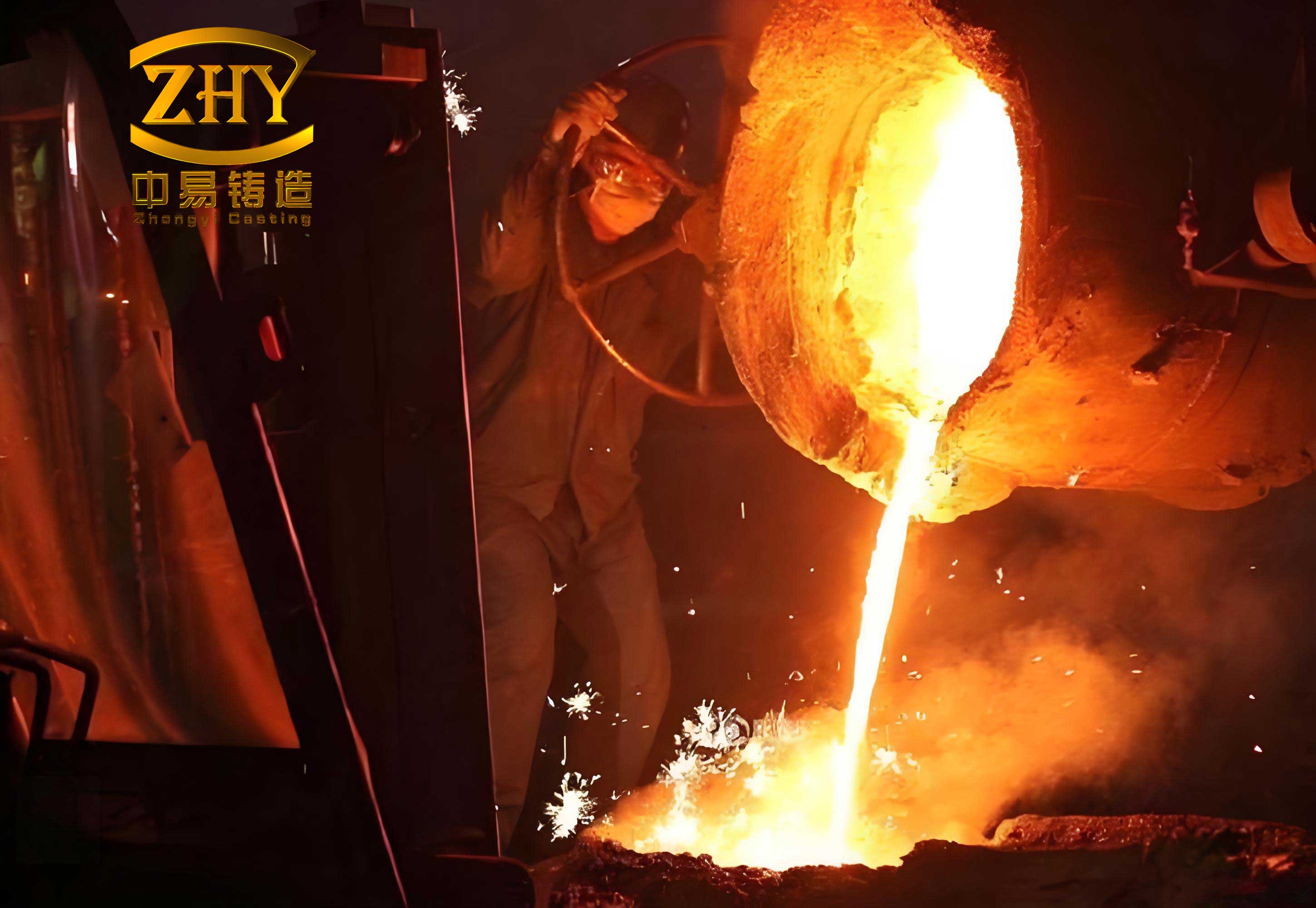
Melting, pouring, and shakeout are where the lost foam casting process culminates. Once the flask is under vacuum (typically 0.4 – 0.6 bar, depending on geometry), pouring commences. The pyrolysis of the foam pattern endothermically decomposes the polymer, requiring a higher pouring temperature ($T_{pour,LFC}$) compared to conventional sand casting ($T_{pour,conv}$). The difference ($\Delta T$) accounts for the energy absorbed by decomposition:
$$
T_{pour,LFC} = T_{pour,conv} + \Delta T \quad \text{where} \quad \Delta T \approx 30 – 100 °C
$$
Thinner sections require higher superheat to prevent mist runs, while thicker sections may use a slightly lower temperature to control shrinkage. After pouring, the vacuum is maintained for a specified “hold time” to allow the casting to solidify under pressure. The flask residence time before shakeout is then adjusted based on casting modulus (volume/surface area) to prevent distortion. Only after cooling is the vacuum released, the film removed, and the flask moved to the shakeout station where the dry, unbonded sand flows freely for reclamation.
| Casting Feature | Pouring Temp. Adjustment | Vacuum Level | Flask Residence Time |
|---|---|---|---|
| Thin Wall (< 10mm) | Higher (+50°C above conv.) | Higher (~0.6 bar) | Shorter |
| Medium Wall (10-25mm) | Moderate (+30°C above conv.) | Medium (~0.5 bar) | Moderate |
| Thick Wall (>25mm) | Standard to Low | Lower (~0.4 bar) | Longer (prevents hot tears) |
The final step for ferrous railroad components is heat treatment. After cleaning, castings undergo a stress-relief annealing or normalizing cycle. Due to the slightly faster cooling inherent in the unbonded sand mold of the lost foam casting process, the annealing temperature is often set 10-30°C higher than for sand castings to ensure complete recrystallization and stress relief. The required保温 time ($t_{soak}$) is a function of the thickest section ($d_{max}$):
$$
t_{soak} = k \cdot (d_{max})^n
$$
where $k$ and $n$ are material- and furnace-dependent constants. This ensures mechanical properties like hardness and tensile strength meet the required standards.
In conclusion, the advanced development of the lost foam casting process has decisively addressed the dimensional variability often associated with traditional green sand casting. For critical railroad track components, this means as-cast dimensions are stable, and mating surfaces with the rail require no secondary machining. The enclosed nature of the production line, with integrated dust collection, has revolutionized the factory environment, reducing particulates and improving safety. Furthermore, the efficient use of floor space, shorter lead times, and lower operational costs solidify its economic viability. Mastering the lost foam casting process is an exercise in accumulated experience and rigorous control. Each product demands a finely tuned set of parameters, and consistent execution at every stage—from bead to heat treatment—is non-negotiable. It is my firm belief that with continued refinement and adherence to these principles, lost foam casting will see ever-broader adoption, potentially replacing traditional methods for an increasing range of components, thereby elevating both product quality and the very nature of the foundry industry.