
In the competitive landscape of manufacturing, particularly for large steel castings, the adoption of the lost foam casting process presents a compelling alternative to traditional wood pattern methods. The core advantages—significantly lower cost for patterns and drastically reduced lead time for preparing molds—are especially beneficial for handling small-batch orders with tight margins. However, the application of this process to large, geometrically complex castings introduces a critical technical challenge: the inherent insufficiency of the expanded polystyrene (EPS) foam model’s strength. This weakness manifests destructively during the resin sand molding stage, a core phase of the lost foam casting process. The combined mechanical pressure from the compacting resin sand and the thermal load from the exothermic curing reaction often leads to model deformation, surface ablation, and severe difficulty during pattern withdrawal. These failures directly translate to defective sand molds with poor dimensional accuracy and surface finish, ultimately compromising final casting quality and negating the initial cost benefits. This persistent issue demanded a systematic, rather than iterative, problem-solving approach. Consequently, I turned to the Theory of Inventive Problem Solving (TRIZ), a powerful methodology for analyzing complex technical contradictions and generating innovative solution concepts.
The lost foam casting process for large castings, as implemented here, diverges from the single-use, negative-pressure approach. To make the foam pattern reusable (akin to a wooden pattern), it is manufactured through a multi-step procedure. A digital CAD model is sectioned into numerous blocks. These blocks are then machined from EPS foam boards, assembled using adhesive, and coated with a refractory slurry to create the final, robust pattern. This pattern is placed in a flask, around which resin-coated sand is poured and compacted. After the resin cures, the foam pattern must be successfully withdrawn to leave behind the intended cavity. The system’s primary function is to transform loose resin sand into a precise, cured sand mold. A functional model of this system reveals the problematic interactions:
| System Component | Primary Function | Interaction with Foam Model | Nature of Interaction |
|---|---|---|---|
| Resin Sand | To fill and form the mold | Applies mechanical pressure during pouring/compaction; releases heat during curing. | Harmful (causes stress & thermal degradation) |
| Compaction Tool | To compact the sand | Transmits kinetic energy to sand, increasing pressure on model. | Harmful (indirectly increases load) |
| Foam Model | To define mold cavity geometry | Must withstand sand pressure and heat without deforming. | Insufficient (property deficiency) |
| Curing Reaction | To solidify the sand mold | Generates exothermic heat transferred to the foam. | Harmful (causes ablation/warping) |
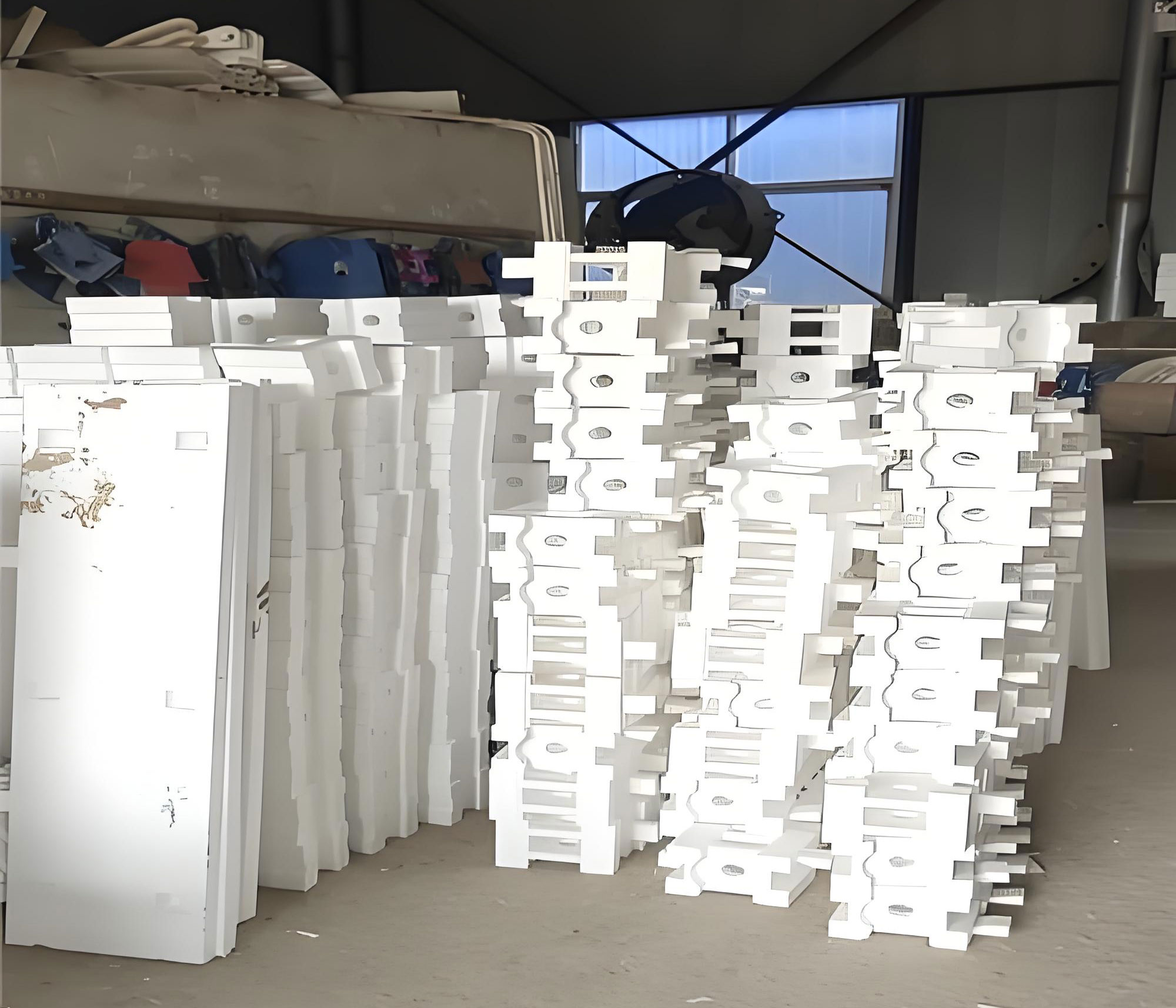
The core problem, “Insufficient foam model strength,” was dissected using TRIZ Causal Chain Analysis to identify root causes. This logical breakdown is crucial for moving beyond symptomatic fixes.
| Primary Effect | Immediate Cause | Root Cause |
|---|---|---|
| Foam Model Deformation/Failure | High mechanical pressure from resin sand. | 1. Sand compaction force. 2. Lack of internal model support. |
| High thermal load causing ablation. | 3. Exothermic resin curing reaction. 4. Inefficient mold cooling. | |
| Low inter-block bonding strength. | 5. Adhesive strength limits; lack of mechanical fastening. | |
| Inhomogeneous model structure. | 6. Variable foam density. 7. Non-uniform coating thickness. | |
| High withdrawal friction/stiction. | 8. Sand adhesion to coating; model deformation increasing contact area. |
From this analysis, five key root causes were targeted for solution generation: Excessive sand pressure, high sand temperature, poor block bonding, low foam density, and structural inhomogeneity. Initial concepts emerged directly: reinforcing surfaces with plates (Solution 1), reducing sand density (Solution 2), and adding mechanical fasteners between blocks (Solution 3).
To generate more sophisticated solutions, I employed the TRIZ contradiction matrix. A technical contradiction arises when improving one parameter of a system worsens another. The first contradiction addressed structural inhomogeneity.
| Contradiction 1: Improving Coating Uniformity vs. Maintaining Shape |
|---|
| Improving Feature (Parameter 13): Stability of the object’s composition. |
| Worsening Feature (Parameter 12): Shape of the object. |
| Inventive Principles Suggested: 1. Segmentation, 22. “Blessing in Disguise”, 18. Mechanical Vibration, 4. Asymmetry. |
| Derived Solutions: • Solution 4 (Segmentation): Segment the pattern function. Use a rigid match plate for complex curved sections and EPS only for simple, flat sections. • Solution 5 (Mechanical Vibration): Place the pattern on a vibrating table during slurry coating to achieve uniform thickness and eliminate voids. |
The second contradiction tackled the thermal damage root cause.
| Contradiction 2: Improving Model Strength vs. Minimizing Material Loss |
|---|
| Improving Feature (Parameter 14): Strength. |
| Worsening Feature (Parameter 23): Loss of substance (e.g., reduced sand reclamation due to cooling). |
| Inventive Principles Suggested: 3. Local Quality, 5. Merging, 28. Mechanics Substitution, 31. Porous Materials, 40. Composite Materials. |
| Derived Solutions: • Solution 6 (Local Quality): Apply strategic over-dimensioning (pre-deformation) on areas prone to thermal sinking. • Solution 7 (Local Quality/Composite): Apply a localized, high-strength, thermally insulating coating to critical zones. • Solution 8 (Porous Materials): Create a porous structure within the foam (e.g., drilled holes) and backfill it with resin sand. This creates internal “stress pillars” and insulates the core foam. The filler’s strength $$S_{composite}$$ can be approximated as a function of the foam and filler strengths: $$S_{composite} = V_f \cdot S_f + V_r \cdot S_r$$ where $$V_f$$ and $$V_r$$ are volume fractions and $$S_f$$ and $$S_r$$ are the strengths of foam and filler resin sand, respectively. |
Next, I applied Substance-Field (Su-Field) modeling, which analyzes interactions between a Tool (S1), a Product (S2), and an Energy field (F). Incomplete or harmful interactions require “standard solutions.” The first harmful interaction was mechanical pressure during withdrawal.
| Su-Field Model 1: Insufficient Withdrawal Strength |
|---|
| Model: S1 (Foam Model) ← F (Mechanical Stress) → S2 (Cured Sand Mold). The stress field causes model failure. Standard Solution: Introduce an internal additive S3 (and a new field F2 if needed) to block the harmful effect. Derived Solutions: • Solution 9: Add smooth, non-stick facing plates on parting surfaces (S3 reduces friction F). • Solution 10: Integrate “withdrawal belts” or strong ribs onto thin-walled sections (S3 provides localized reinforcement). • Solution 11: Add sacrificial “withdrawal bosses” (S3) with large cross-sections to the pattern, to be cut off and repaired in the mold later. • Solution 12: Embed a rigid internal skeleton (S3) into the foam, with built-in lifting points. |
The second harmful interaction was thermal damage.
| Su-Field Model 2: Thermal Degradation |
|---|
| Model: S1 (Foam Model) ← F (Thermal Energy) ← S2 (Hot Sand). The heat field damages S1. Standard Solution: Introduce an additive S3 between S1 and S2 to block the harmful effect. Derived Solution 13: Insert wooden plugs or ceramic pieces (S3) into deep sections of the foam model. These act as thermal barriers and structural supports, reducing the heat flux $$q$$ experienced by the foam: $$q = \frac{T_{sand} – T_{foam}}{R_{total}}$$ where the total thermal resistance $$R_{total}$$ is increased by the plug’s resistance. |
Thirteen potential solutions were generated. A weighted evaluation matrix was used to select the most viable combination for implementation in the lost foam casting process. The criteria were weighted based on industrial priorities: Effect (40%), Cost (30%), Implementation Difficulty (20%), and Lead Time (10%). Each solution was scored from 1 (Poor) to 10 (Excellent).
| Solution # & (Source) | Brief Description | Effect (40%) | Cost (30%) | Difficulty (20%) | Time (10%) | Total Score |
|---|---|---|---|---|---|---|
| 10 (Su-Field 1) | Add withdrawal belts/ribs to thin sections. | 10 | 8 | 8 | 5 | 8.5 |
| 7 (Contradiction 2) | Apply local high-strength insulating coating. | 10 | 9 | 6 | 4 | 8.3 |
| 11 (Su-Field 1) | Add sacrificial withdrawal bosses. | 7 | 8 | 8 | 7 | 7.5 |
| 1 (Causal Chain) | Reinforce surface with replaceable plates. | 9 | 6 | 9 | 3 | 7.5 |
| 8 (Contradiction 2) | Create porous structure & backfill with sand. | 9 | 9 | 8 | 5 | 8.7 |
| 6 (Contradiction 2) | Strategic pre-deformation (over-dimensioning). | 6 | 9 | 8 | 5 | 7.2 |
The evaluation revealed that Solution 8 (Porous Backfill) scored highest. The optimal strategy became a synergistic combination of the top-performing concepts: Implementing a porous, backfilled core structure (S8) for global strength and thermal insulation, complemented by local reinforcement using withdrawal belts on thin walls (S10) and replaceable wear plates on high-pressure surfaces (S1). This integrated approach simultaneously addresses multiple root causes: the backfill resists pressure and heat, the belts prevent localized deformation, and the plates protect high-wear areas, all while maintaining reasonable cost and implementability.
Implementing this combined solution within our lost foam casting process required specific design rules. The porous pattern was achieved by drilling a grid of holes (covering 15-20% of the volume) into thick sections of the EPS model before assembly and coating. These holes were then filled with loose, resin-coated sand during the molding process itself, which then cured as part of the mold wall. The relationship for the enhanced compressive strength $$\sigma_c$$ of this composite section can be modeled as: $$\sigma_c = (1 – \phi) \cdot \sigma_{foam} + \phi \cdot \sigma_{sand}$$ where $$\phi$$ is the volume fraction of sand filler and $$\sigma_{foam}$$ and $$\sigma_{sand}$$ are the respective compressive strengths. Furthermore, the insulating effect increases the thermal time constant $$\tau$$ for the foam core: $$\tau \propto \frac{\rho \cdot c_p \cdot L^2}{k_{eff}}$$ where $$k_{eff}$$ is the lowered effective thermal conductivity due to the disrupted foam matrix.
The results were measured across multiple production runs of large valve bodies and turbine housings. The primary metric—foam pattern survival rate for reuse—increased from under 40% to over 85%. Dimensional inspection of the resultant sand molds showed a reduction in size deviation from ±4.5mm to within ±1.5mm on critical features. Surface finish quality improved by two grades, significantly reducing post-casting cleaning and grinding costs. The slight increase in pattern manufacturing time was offset by the drastic reduction in mold repair and pattern replacement activities, leading to a net reduction in total cost per mold of approximately 22%.
This systematic journey from a chronic production ailment to a robust, optimized solution underscores the profound utility of the TRIZ methodology in advanced manufacturing contexts like the lost foam casting process. By forcing a structured analysis through functional and causal lenses, then providing generative tools like the contradiction matrix and Su-Field models, TRIZ moves problem-solving beyond intuitive guesswork. It efficiently explores the solution space across physical, chemical, and geometric dimensions. The successful integration of the derived concepts—particularly the composite porous-backfill structure—not only solved the immediate strength issue but also delivered unexpected benefits in thermal management within the lost foam casting process. This case demonstrates that TRIZ is not merely a theoretical framework but a potent engineering toolkit for developing innovative, patentable, and highly effective solutions to persistent industrial challenges, ensuring the economic and technical viability of critical manufacturing processes.