
The production of high-quality, durable zinc ingot molds is a critical challenge in non-ferrous metal casting. These molds, serving as consumable components in disc casting machines, are subjected to severe service conditions including mechanical impact, thermal shock from molten zinc, and cyclic heating and cooling. Their performance directly dictates the surface finish, dimensional accuracy, and production efficiency of the final zinc ingots. Traditional methods, such as resin sand casting, often result in molds with inherent limitations: rough casting surfaces leading to poor zinc ingot finish, dimensional instability (particularly in delicate features like lifting lugs), and the formation of surface pores that cause zinc adhesion and difficult demolding. These shortcomings necessitate frequent mold replacement, increasing operational costs and downtime.
This detailed practice explores the application of lost foam casting (LFC) as a superior alternative for manufacturing zinc ingot molds. The lost foam casting process, characterized by its ability to produce castings with excellent dimensional accuracy, superior surface finish, and complex geometries with reduced machining requirements, presents a theoretically ideal solution. This report documents a complete production cycle, from initial design and process planning to final quality validation, establishing the practical feasibility and quantifying the benefits of employing lost foam casting for this specific component.
1. Component Analysis and Material Selection
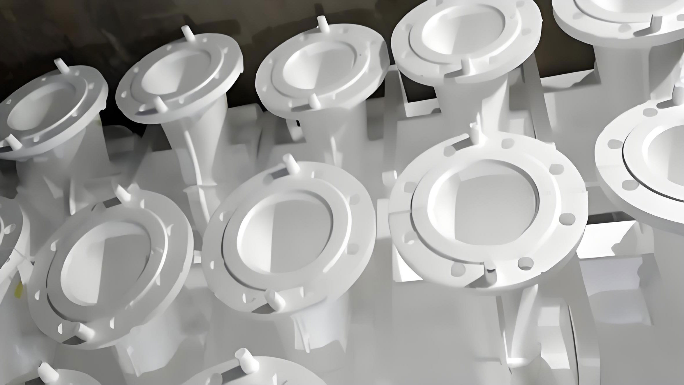
The zinc ingot mold is a relatively simple, pan-shaped casting. Its key dimensions are approximately 630 mm in length, 305 mm in width, with wall thicknesses ranging from a minimum of 22 mm to a maximum of 46 mm. The nominal weight of the finished ferrous casting is 55 kg. The primary functional requirement is an impeccably smooth and flat internal cavity, free from defects like blow holes, sand inclusions, cracks, or surface irregularities, as this cavity forms the surface of the zinc ingot.
Material selection is paramount. Compacted Graphite Iron (CGI), specifically grade RuT300, was chosen over traditional gray iron or ductile iron. RuT300 offers a unique combination of properties beneficial for this application:
- Thermal Fatigue Resistance: The vermicular graphite structure provides superior thermal conductivity and resistance to growth under thermal cycling compared to flake graphite, reducing the risk of heat checking.
- Surface Finish: The metal matrix associated with CGI generally yields a better as-cast surface finish than gray iron.
- Mechanical Properties: It offers higher tensile strength and elongation than gray iron, providing better resistance to mechanical knocks and impacts during handling.
- Castability: Its solidification shrinkage behavior is intermediate between gray and ductile iron, helping to minimize shrinkage defects and hot tearing, which is crucial for the relatively thin-walled mold structure.
The mold also requires a final heat treatment (quenching and tempering) to achieve the desired hardness and toughness profile for extended service life.
2. Lost Foam Casting Process Design and Principles
The core principle of lost foam casting involves creating a foam polymer pattern of the desired part, coating it with a refractory ceramic slurry, embedding it in unbonded sand, and then pouring molten metal. The metal vaporizes the foam pattern, exactly replacing its volume to form the casting. For the zinc ingot mold, a vertical pouring orientation was selected to optimize filling and solidification control.
2.1 Gating System Design and Rationale
The design goal was to achieve directional solidification favoring the ingate areas and minimize thermal gradients that could lead to shrinkage porosity or distortion. Given the mold’s length (630mm) exceeding 400mm, a single ingate was deemed insufficient for clean, rapid filling. Therefore, a system with two side ingates was designed to ensure balanced metal entry and uniform temperature distribution.
The gating system was sized based on empirical relations and the modulus of the casting. The modulus (Volume/Surface Area) is a key factor in predicting solidification time. For a thin-walled section like our mold, the filling speed must be high enough to prevent premature freezing of the metal front. The choke area (the smallest cross-sectional area in the gating system, typically at the ingates) was calculated to ensure a desired fill time. An initial fill time (t) of 10-15 seconds was targeted. The required choke area (Ac) can be estimated using the formula:
$$A_c = \frac{W}{\rho \cdot v \cdot t}$$
Where:
- W = Weight of the casting (+ pattern) ≈ 60 kg (including foam)
- ρ = Density of molten iron ≈ 7,000 kg/m³
- v = Theoretical flow velocity (controlled by applied vacuum and head pressure)
- t = Desired fill time (e.g., 12 s)
This calculation provided a basis for sizing. The final designed dimensions were:
- Ingates: Truncated pyramid shape: top 25×40 mm, bottom 40×40 mm, height 60 mm. The tapered design helps reduce turbulence.
- Runner: 40×40 mm cross-section, 100 mm long, connecting two molds in a cluster to improve yield.
- Sprue: 40×40 mm cross-section, 500 mm height to provide sufficient metallostatic pressure head for mold filling.
| Gating Element | Cross-Section (mm) | Length/Height (mm) | Primary Function |
|---|---|---|---|
| Sprue | 40 x 40 | 500 | Provide metallostatic pressure head |
| Runner | 40 x 40 | 100 | Distribute metal to multiple ingates |
| Ingate (each) | Top: 25×40, Bottom: 40×40 | 60 | Control fill rate, introduce metal into cavity |
2.2 Foam Pattern Production and Assembly
Expandable Polystyrene (EPS) beads with a density range of 16-20 kg/m³ were used to produce the patterns. A pattern contraction allowance of 1.0% was applied to all dimensions to compensate for the solidification shrinkage of RuT300 iron. Strict quality control was enforced on the foam patterns:
- No surface defects like dents, projections, missing sections, or warpage were permitted.
- Minor imperfections were carefully repaired using specialized foam fillers and sanding tools.
- Pattern density was verified by weight and volume checks; lower density can lead to pattern collapse, while higher density increases gas evolution during pouring.
The assembly of the gating system to the pattern is a critical step in lost foam casting. A fast-setting, low-residue adhesive was used. Precise alignment was crucial to ensure proper metal flow. Excess adhesive, which can create surface defects on the final casting (known as “glue streaks”), was meticulously avoided.
2.3 Ceramic Coating Application
The ceramic coating serves multiple vital functions in lost foam casting: it provides a barrier between the sand and the molten metal, enhances pattern strength for handling, allows gases from the decomposing foam to permeate out, and controls the cooling rate of the metal. A proprietary water-based refractory coating designed for cast iron was employed.
The coating process parameters were tightly controlled:
- Slurry Consistency: Maintained at a Baume density of 60-70°Bé for dipping/brushing.
- Application: Applied via dipping and brushing in three consecutive layers.
- Drying: Each layer was completely dried (<5.0% moisture content as measured by a moisture analyzer) before applying the next. Incomplete drying leads to gas generation and coating peel-off.
- Final Thickness: Target dry coating thickness was 2.0-2.5 mm. This is calculated based on the surface area (As) of the pattern and the volume of coating solids (Vc) deposited. An approximate relation is:
$$ \text{Coating Thickness} (t_c) \approx \frac{V_c}{A_s} $$
A uniform, crack-free coating is essential. Cracks can lead to metal penetration and rough casting surfaces (“vermiculation” defect). The sound of a dry coating when tapped is a clear, sharp ring.
| Coating Layer | Target Baume Density (°Bé) | Key Quality Check | Purpose |
|---|---|---|---|
| First Layer | 65-70 | Complete coverage, no “white spots” | Create primary barrier, anchor to foam |
| Second Layer | 62-67 | Repair any cracks from first layer | Build thickness, improve strength |
| Third Layer | 60-65 | Final thickness 2.0-2.5 mm, no drips | Ensure integrity, control permeability |
2.4 Sand Molding and Compaction
Dry, unbonded silica sand (AFS GFN ~55) was used for molding. The coated pattern cluster was placed in a vented flask. Sand was poured around the pattern in stages, with systematic vibration applied after each stage to achieve maximum and uniform compaction. Inadequate compaction can cause wall movement or complete collapse (fold defect) when the foam vaporizes. The vibration sequence was:
- First Compaction: After placing a base layer of sand.
- Second Compaction: When sand covered about two-thirds of the pattern height.
- Third Compaction: After sand filled up to the top of the pouring basin.
- Final Compaction: After completely filling the flask.
Each vibration lasted at least 3 minutes. After molding, a plastic film was placed over the sand surface to create an effective seal when vacuum is applied.
3. Melting, Pouring, and Post-Processing
3.1 Charge Make-up and Melt Control
The RuT300 iron was melted in a medium-frequency induction furnace. The charge consisted of a blend of specialized pig iron (low in trace elements detrimental to CGI), steel scrap, and necessary alloying elements (Ferrosilicon, etc.). Precise control of chemistry, particularly the levels of carbon, silicon, and magnesium/cerium (for vermicularization), is critical. A late inoculation was performed in the ladle to promote the desired compacted graphite structure. The target chemical composition range is shown below.
| Element | Target Range (wt.%) | Function |
|---|---|---|
| Carbon (C) | 3.4 – 3.6 | Graphite former, affects fluidity and shrinkage |
| Silicon (Si) | 2.4 – 3.0 | Graphitizer, strengthens ferrite matrix |
| Manganese (Mn) | 0.4 – 0.6 | Strengthens pearlite, counteracts sulfur |
| Chromium (Cr) | 2.2 – 2.5 | Promotes pearlite, increases hardness & wear resistance |
| Phosphorus (P) | ≤ 0.07 | Impurity, reduces toughness if high |
| Sulfur (S) | ≤ 0.06 | Impurity, interferes with graphite formation |
| Vermiculizer (e.g., Mg, Ce) | Trace (Controlled) | Inhibits spheroidization, promotes vermicular graphite |
3.2 Pouring Practice in Lost Foam Casting
This phase is where the distinct characteristics of lost foam casting are fully realized. The process parameters are interlinked:
- Pouring Temperature: Carefully controlled at 1450-1460°C. Too low a temperature risks misruns due to premature freezing of the metal front advancing through the foam pattern. Too high a temperature increases the rate of foam decomposition, potentially overwhelming the coating’s permeability and leading to porosity defects. The temperature drop from tapping (1520-1530°C) to pouring accounts for ladle preheat and handling time.
- Vacuum Application: A critical parameter. The vacuum pump was started 10 minutes before pouring to establish a stable negative pressure field within the sand mass, typically at 0.60-0.70 MPa. This vacuum serves multiple purposes:
- It draws the decomposed foam gases through the coating and away from the metal front via the vented flask.
- It consolidates the unbonded sand, increasing its effective strength to resist metal pressure.
- It assists in drawing the molten metal into the cavity, especially in thin sections. During pouring, the vacuum was maintained at 0.40-0.60 MPa. The relationship between vacuum pressure (Pv), sand permeability (k), and gas flow rate (Q) is complex but can be conceptually simplified. A sufficient vacuum level ensures:
$$ Q \propto \frac{k \cdot A \cdot \Delta P}{\mu \cdot L} $$
where ΔP is the pressure differential (atmospheric + vacuum), A and L are the cross-sectional area and length of the gas escape path through the coating and sand, and μ is the gas viscosity. An optimal vacuum level must be found; too high can cause penetration of liquid metal into the sand.
- Pouring Rate: The pour was conducted swiftly and continuously to fill the mold within the target 10-15 second window, preventing collapse of the unfilled mold cavity.
3.3 Shakeout, Cleaning, and Heat Treatment
After pouring, the casting was allowed to solidify and cool in the flask for approximately 12 hours to below 500°C before shakeout. The unbonded sand falls away easily, leaving the casting with the attached gating system. This is a significant advantage of lost foam casting, eliminating the need for aggressive knockout operations. The castings were then shot blasted to remove any residual coating film. The gating system was removed via abrasive cutting and grinding. Finally, the molds underwent a quenching and tempering heat treatment to achieve the required mechanical properties:
- Austenitizing at 900°C for 2 hours.
- Quenching in water to form a martensitic structure.
- Tempering at 360°C for 4 hours to relieve stresses and achieve a tempered martensite microstructure with good hardness and toughness.
4. Results, Analysis, and Discussion
4.1 Dimensional Accuracy and Surface Quality
Castings produced via the lost foam casting process exhibited exceptional dimensional consistency and surface finish. The internal cavities of the molds were smooth and flat, with clearly defined lettering. The average surface roughness (Ra) measured was 3.2 μm, a significant improvement over the 6.3 μm typical of resin sand castings. This improvement is attributed to the absence of a parting line and the replication of the smooth foam pattern surface by the ceramic coating and subsequently the metal. Dimensional variation was within the 1.0% pattern allowance, confirming the stability of the process.
4.2 Metallurgical and Mechanical Properties
Spectroscopic analysis confirmed that the final castings met the RuT300 chemical specifications. The microstructure of the as-cast material (prior to heat treatment) showed a matrix of pearlite and ferrite with a predominant amount of vermicular (compacted) graphite, approximately 65% as per standard microstructure assessment charts, alongside some nodular graphite. This structure is ideal for the application.
Mechanical testing after heat treatment revealed superior properties compared to traditional cast molds:
| Property | Lost Foam Cast Mold (Average) | Traditional Resin Sand Cast Mold (Average) | Improvement | Test Standard |
|---|---|---|---|---|
| Tensile Strength | 374 MPa | 192 MPa | +95% | GB/T 228.1 |
| Elongation | 3.85% | 2.00% | +93% | GB/T 228.1 |
| Surface Hardness (HBW) | 174 | 134 | +30% | GB/T 231.1 |
| Surface Roughness (Ra) | 3.2 μm | 6.3 μm | ~50% smoother | GB/T 15056 |
The significant increase in tensile strength and hardness cannot be attributed solely to the material specification. A key phenomenon in lost foam casting is surface alloying or carburization. As the EPS foam pattern thermally decomposes in the presence of molten iron, it generates a reducing atmosphere rich in carbonaceous gases (e.g., styrene, benzene, and free carbon). Some of this carbon diffuses into the surface layer of the solidifying casting, creating a harder, more wear-resistant case. The effective case depth (CHeff) can be influenced by factors like coating permeability, pouring temperature, and carbon potential of the pyrolysis gases. This in-situ created wear layer is a major contributor to the extended service life.
4.3 Defect Analysis and Process Yield
The first-run yield for acceptable castings directly after shakeout exceeded 75%. After minor grinding and finishing of inconsequential surface imperfections, the overall yield reached over 80%. The primary defects observed and their root causes in the lost foam casting process were:
- Surface Slag/Carbon Inclusions: Caused by incomplete evacuation of foam pyrolysis products, often linked to insufficient coating permeability, low pouring temperature, or inadequate vacuum.
- Minor Shrinkage Porosity: Occurred in isolated heavy sections, indicating a need for slight adjustments to the gating/feeding design to promote more directional solidification.
These issues were systematically addressed through iterative process refinement, such as adjusting coating viscosity and ensuring complete pattern coating dryness.
| Defect Type | Likely Cause in Lost Foam Casting | Corrective Action |
|---|---|---|
| Vermiculation (Worm-like projection) | Coating crack or local failure, allowing sand penetration | Improve coating application/drying; ensure vibration does not damage coating |
| Folds or Collapses | Insufficient sand compaction; pour rate too slow | Increase vibration time/energy; optimize pour speed |
| Blow Holes | Wet coating; high pattern density; low vacuum | Ensure coating dryness; control foam density; maintain vacuum protocol |
4.4 Service Life Performance
Field data from customer use provided the most critical validation. Zinc ingot molds produced by this lost foam casting process demonstrated an average service life of approximately 8 months under standard production conditions. This represents a 15% increase in lifespan compared to molds produced by the conventional resin sand method. This extension is directly attributable to the synergistic combination of:
- The superior high-temperature mechanical properties of the RuT300 material.
- The enhanced surface hardness from the lost foam casting-induced carburization effect.
- The excellent surface finish, which reduces the nucleation sites for zinc adhesion and thermal fatigue cracking.
The economic benefit is substantial, reducing mold changeover frequency, maintenance downtime, and overall cost per ton of zinc produced.
5. Conclusion
This comprehensive production practice has conclusively demonstrated the technical and commercial viability of using the lost foam casting process for manufacturing zinc ingot molds. The process successfully overcomes the limitations of traditional casting methods by delivering:
- Castings with exceptional dimensional accuracy and a superior as-cast surface finish (Ra 3.2 μm).
- Enhanced metallurgical properties, including an average tensile strength of 374 MPa and a bulk hardness of 174 HB, further augmented by a wear-resistant carburized surface layer inherent to the lost foam casting process.
- A robust and repeatable process capable of achieving a first-pass yield greater than 75% and a final yield over 80%.
- A significant 15% extension in service life as validated in industrial application, leading to tangible operational cost savings.
The success of this project hinged on the integrated optimization of all lost foam casting parameters: precise foam pattern quality, controlled application of a permeable ceramic coating, disciplined sand compaction, and tight control over melting, pouring temperature, and vacuum dynamics. This practice serves as a validated model for adopting lost foam casting for other high-wear, thermally cycled cast iron components, highlighting its potential to improve product performance and manufacturing efficiency.