
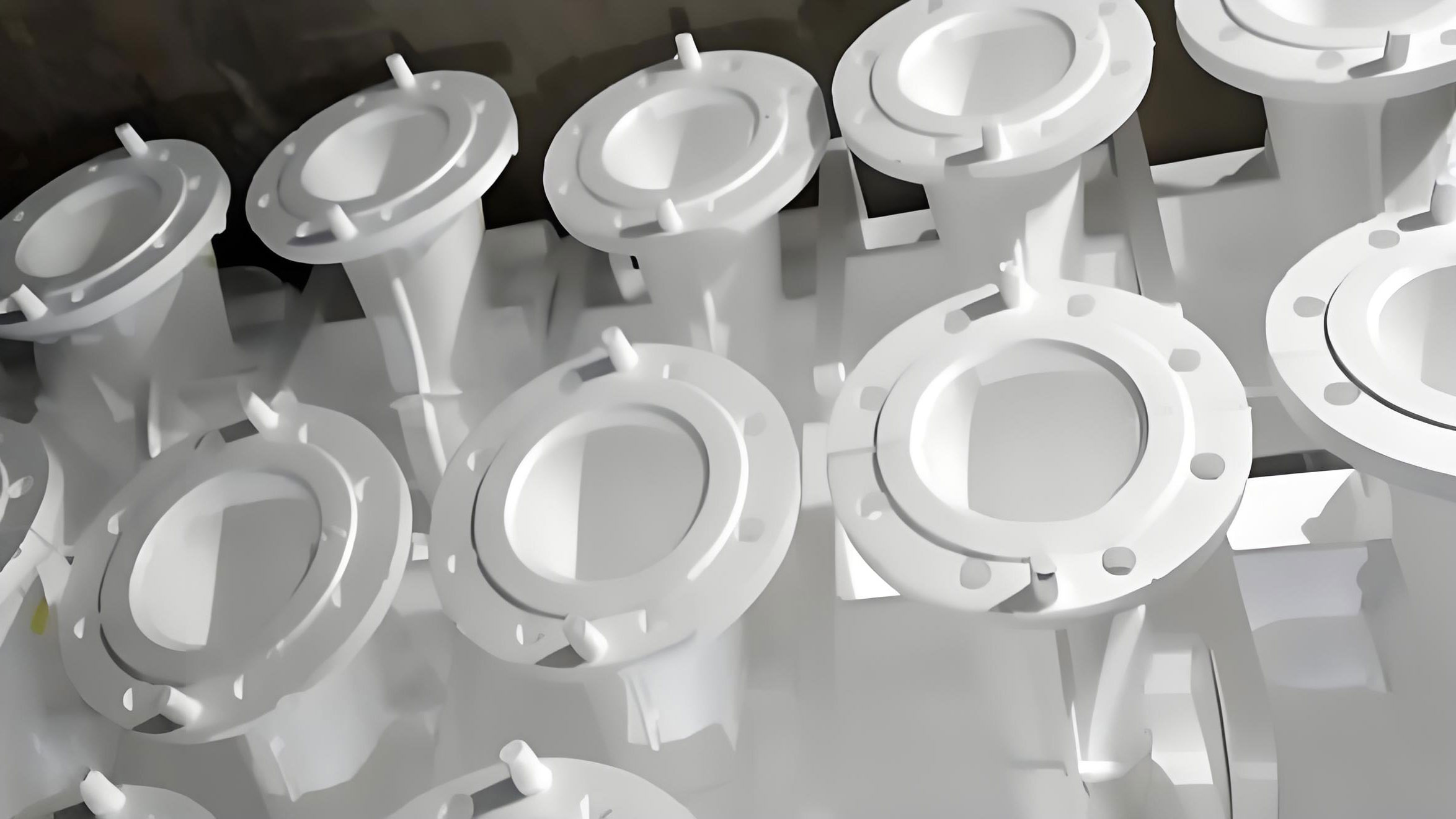
The lost foam casting (LFC) process, a significant advancement over conventional sand casting methods, utilizes expendable foam patterns to produce complex, near-net-shape metal components. In this process, a foam pattern, typically made of expandable polystyrene (EPS), is coated with a refractory slurry, embedded in unbonded dry sand, and then replaced by molten metal during pouring. The metal’s heat causes the foam to thermally degrade and vaporize, allowing the metal to fill the cavity precisely. This methodology offers distinct advantages, including exceptional design freedom for intricate geometries, high dimensional accuracy, excellent surface finish, and simplified production flow by eliminating cores and parting lines. Consequently, lost foam casting has been widely adopted in manufacturing critical automotive components, such as transmission housings, which are characterized by complex internal passages and stringent quality requirements.
However, the production of heavy-duty transmission housings via lost foam casting presents significant technical challenges, primarily concerning dimensional stability and the control of deformation defects. These castings often feature substantial variations in wall thickness, large planar surfaces, and unsupported internal cavities. During the LFC process sequence—encompassing pattern assembly, coating, sand filling and compaction, and metal pouring—these structural characteristics can lead to pattern distortion, ultimately resulting in defective castings. This paper, based on extensive production experience and analysis, systematically investigates the root causes of deformation in such components and presents a multi-faceted optimization strategy. The implemented measures have demonstrably reduced the scrap rate due to deformation from 2.63% to 0.33%, offering a reliable framework for quality control in the lost foam casting of complex structural parts.
Root Cause Analysis of Deformation in Lost Foam Casting
The deformation of a casting in the lost foam casting process is not attributable to a single factor but is the cumulative result of interactions between the component’s design, the properties of the foam pattern, and specific process parameters. A thorough understanding of these contributing elements is essential for developing effective countermeasures.
1. Structural Design of the Casting
The geometry of a heavy-duty transmission housing is inherently prone to deformation. A typical housing can have a height exceeding 590 mm with a main body section of approximately 415 mm. The wall thickness can vary dramatically, from minimal sections of 8 mm to bulky regions as thick as 60 mm. This non-uniform mass distribution creates significant differential cooling during solidification. Thicker sections cool and solidify slower, undergoing more substantial volumetric shrinkage compared to the rapidly cooling thin sections. This imbalance generates internal thermal stresses, often manifesting as warpage or distortion, particularly in large, flat areas like the top cover flange. Furthermore, the main housing body frequently incorporates large, unsupported internal cavities. The lack of internal reinforcing ribs compromises the pattern’s structural rigidity during the crucial stages of coating, sand compaction, and metal filling, making these areas susceptible to collapse or bending under external forces.
2. Process-Induced Deformation Mechanisms
The sequential nature of the lost foam casting process introduces several opportunities for pattern distortion before metal ever enters the mold.
a) Coating Application (Dipping): The application of the refractory coating via dipping is a critical step. The buoyancy force \( F_b \) exerted on the foam pattern by the coating slurry can be approximated by Archimedes’ principle:
$$ F_b = \rho_{slurry} \cdot g \cdot V_{displaced} $$
where \( \rho_{slurry} \) is the density of the coating slurry, \( g \) is gravity, and \( V_{displaced} \) is the volume of the submerged portion of the pattern. Since EPS foam has a very low density (typically 20-25 kg/m³), the buoyant force can be significant relative to the pattern’s weight. If the pattern’s inherent rigidity is low or the dipping orientation is unfavorable, this force can cause bending or twisting. Additionally, water-based coatings used in lost foam casting exhibit thixotropic behavior; their viscosity \( \eta \) decreases under shear (stirring) and recovers when static. An uncontrolled increase in viscosity during dipping can alter the hydrodynamic forces on the pattern, exacerbating deformation risks.
b) Sand Compaction (Vibration): Dry sand compaction through vibration is necessary to achieve uniform mold density around the complex pattern. However, improper vibration parameters can lead to deformation. The dynamic pressure \( P_d \) exerted by the moving sand on the pattern is influenced by vibration acceleration \( a \), sand density \( \rho_{sand} \), and the geometry of the sand flow path:
$$ P_d \propto \rho_{sand} \cdot a \cdot f(\text{geometry}) $$
Excessive vibration intensity or incorrect sand introduction methods can create localized high-pressure zones, particularly against large, unsupported pattern surfaces, causing them to deflect.
c) Coating Hygroscopicity: Water-based coatings are inherently hygroscopic. When a coated pattern is stored in a high-humidity environment before molding, the coating absorbs moisture from the air. This absorption plasticizes the coating binder, drastically reducing its dry strength and modulus of elasticity \( E_{coating} \). A weakened coating provides diminished support to the underlying foam pattern during the subsequent vibration stage, making the assembly more susceptible to deformation under the pressures of sand compaction.
d) Sand Temperature: The thermal properties of the EPS pattern material are a major concern. The glass transition temperature \( T_g \) of EPS is relatively low (around 100°C). When the dry sand used for molding is at an elevated temperature (e.g., >60°C), the heat transferred to the pattern softens it, reducing its yield strength \( \sigma_y \) and rigidity. A softened pattern is far more likely to deform under the mechanical stresses of sand filling and vibration. The degree of softening can be related to temperature by an Arrhenius-type relationship for polymer viscosity:
$$ \eta(T) = \eta_0 \exp\left(\frac{E_a}{RT}\right) $$
where \( \eta(T) \) is the temperature-dependent viscosity (related to softness), \( \eta_0 \) is a constant, \( E_a \) is the activation energy for flow, \( R \) is the gas constant, and \( T \) is the absolute temperature of the sand in contact with the pattern.
Systematic Optimization Strategy for Deformation Control
Addressing the deformation challenge in lost foam casting requires a holistic approach targeting each identified root cause. The following integrated strategy was developed and implemented.
1. Pattern Reinforcement and Structural Optimization
To counteract the inherent lack of rigidity in large cavity areas, the internal support structure of the foam pattern assembly was redesigned. Several reinforcement schemes were prototyped and tested, moving away from simple parallel foam ribs to more robust configurations. The most effective design involved integrating a “two-horizontal, one-vertical” EPS rib structure directly into the main cavity during the pattern molding stage. This triangular truss-like configuration significantly increases the pattern’s moment of inertia \( I \) and bending stiffness \( D \), where:
$$ D = E_{foam} \cdot I $$
This enhanced stiffness effectively resists deflection during handling and processing. The performance of different reinforcement schemes is summarized in Table 1.
| Scheme Description | Key Feature | Scrap Rate | Assessment |
|---|---|---|---|
| Original: Two Parallel Foam Ribs | Baseline design | 2.63% | Insufficient rigidity |
| Scheme 1: Triangular Fiber Rods | Replaced parallel ribs with triangular layout | 2.98% | Ineffective |
| Scheme 2: One Vertical Fiber Rod | Extended vertical support | 0.96% | Fiber residue caused measurement issues |
| Scheme 3: Three Parallel Fiber Rods | Increased support density | 1.80% | Moderate improvement |
| Scheme 4: Hybrid Fiber/Foam Triangle | Complex multi-layer support | 1.21% | Improved but complex assembly |
| Scheme 5: “Two-Horizontal, One-Vertical” EPS Ribs | Integrated triangular foam structure | 0.84% | Optimal: Effective and process-friendly |
2. Coating Process Enhancement
Modifications to the coating procedure focused on minimizing buoyancy-related distortion.
a) Viscosity Stabilization: To combat thixotropy and maintain a consistent buoyant force \( F_b \), continuous mechanical agitation of the coating slurry was implemented throughout the dipping operation. This ensured the viscosity \( \eta \) remained at a stable, low-shear value, providing predictable fluid dynamics during immersion.
b) Optimized Dipping Orientation: The dipping sequence was strategically revised. The pattern cluster is first immersed with the gating system facing downwards. It is then sequentially rotated to dip one major side and then the other, rather than being submerged in a single orientation. This method reduces the maximum submerged volume \( V_{displaced} \) at any one time, thereby controlling the peak buoyancy force exerted on the most vulnerable sections of the pattern.
3. Precision Vibration Compaction Protocol
The sand filling and vibration parameters were meticulously optimized to ensure adequate compaction while minimizing dynamic pressure \( P_d \) on the pattern. A multi-stage protocol was established, as outlined in Table 2.
| Stage | Sand Fill Height / Target | Vibrator Motor Speed (RPM) | Objective |
|---|---|---|---|
| 1 | Base Sand Layer | 2500 | Establish firm foundation |
| 2 | +150 mm | 2400 | Gentle filling around lower features |
| 3 | +150 mm | 2400 | Controlled filling to mid-height |
| 4 | +150 mm | 2500 | Increased compaction near top cavity |
| 5 | To Pattern Parting Line | 2800 | Final high-intensity compaction for top sand |
This graded approach allows sand to flow steadily into cavities without creating high-velocity impacts, and it delays the application of highest vibration energy until the pattern is largely supported from below.
4. Control of Coating Hygroscopicity
To prevent the weakening of the coating due to moisture absorption, two practical measures were enforced:
1. Immediate Sealing: After drying, each coated pattern cluster is promptly sealed in a plastic barrier bag, isolating it from ambient humidity until the moment it is placed into the molding flask.
2. Work-in-Progress (WIP) Limitation: The number of coated patterns allowed in the molding area is strictly limited to the quantity required for the next immediate pouring batch. This drastically reduces the storage time \( t_{storage} \) in the production environment, minimizing the opportunity for moisture uptake. The relationship between weight gain \( \Delta W \) and time in a humid environment can be modeled as:
$$ \Delta W(t) = M_{\infty} (1 – e^{-kt}) $$
where \( M_{\infty} \) is the maximum moisture uptake and \( k \) is a rate constant. Minimizing \( t \) directly reduces \( \Delta W \) and the associated loss in coating strength.
5. Digital Sand Temperature Management
Recognizing the critical impact of sand temperature \( T_{sand} \) on EPS softening, a digital monitoring and control system was installed. The system provides real-time feedback, ensuring \( T_{sand} \) is maintained below the critical threshold of 60°C at the point of contact with the pattern. This closed-loop control is vital for process consistency, as it maintains the foam’s mechanical properties within a safe window, ensuring it can withstand the vibration compaction forces.
Production Validation and Results
The synergistic implementation of all five optimization strategies was validated through large-scale production of over 85,000 heavy-duty transmission housing castings. The results confirmed a dramatic reduction in deformation-related scrap. The overall scrap rate plummeted from the initial 2.63% to a final stable rate of 0.33%. The incremental contribution of each major intervention is illustrated in Table 3, demonstrating the cumulative effectiveness of the integrated approach.
| Process Optimization Step Implemented | Cumulative Scrap Rate After Implementation | Reduction vs. Previous Step |
|---|---|---|
| Initial Baseline Process | 2.63% | – |
| 1. Pattern Structural Reinforcement (Scheme 5) | 0.84% | 68.1% reduction |
| 2. Coating Process Enhancement | 0.73% | Further 13.1% reduction |
| 3. Vibration Compaction Optimization | 0.50% | Further 31.5% reduction |
| 4. Hygroscopicity Control Measures | 0.40% | Further 20.0% reduction |
| 5. Digital Sand Temperature Control (< 60°C) | 0.33% | Final 17.5% reduction |
Beyond scrap reduction, the improvements led to enhanced dimensional consistency, reduced post-casting rectification work, and increased overall production reliability for these complex lost foam castings.
Conclusion
This investigation into deformation defects within the lost foam casting process for heavy-duty transmission housings demonstrates that a systemic, root-cause-based methodology is essential for effective quality control. The five core strategies—pattern structural optimization, coating process control, precision vibration compaction, mitigation of coating hygroscopicity, and strict thermal management of molding sand—form a comprehensive and interdependent solution set. The successful application of these strategies, validated by a scrap rate reduction from 2.63% to 0.33%, underscores their practical efficacy.
The key to success in lost foam casting of complex, thin-walled, and structurally asymmetric components lies in recognizing the process’s unique sensitivities. Enhancing the foam pattern’s inherent rigidity, carefully managing every fluid and mechanical interaction during processing, and controlling the thermal environment are not isolated tasks but interconnected pillars of a robust manufacturing protocol. This work provides a validated template for tackling deformation challenges, contributing significantly to the advancement of lost foam casting technology for high-integrity, precision automotive components. The principles established here are widely applicable to other complex geometries produced via the lost foam casting process, promoting its potential for greater adoption in precision manufacturing sectors.