
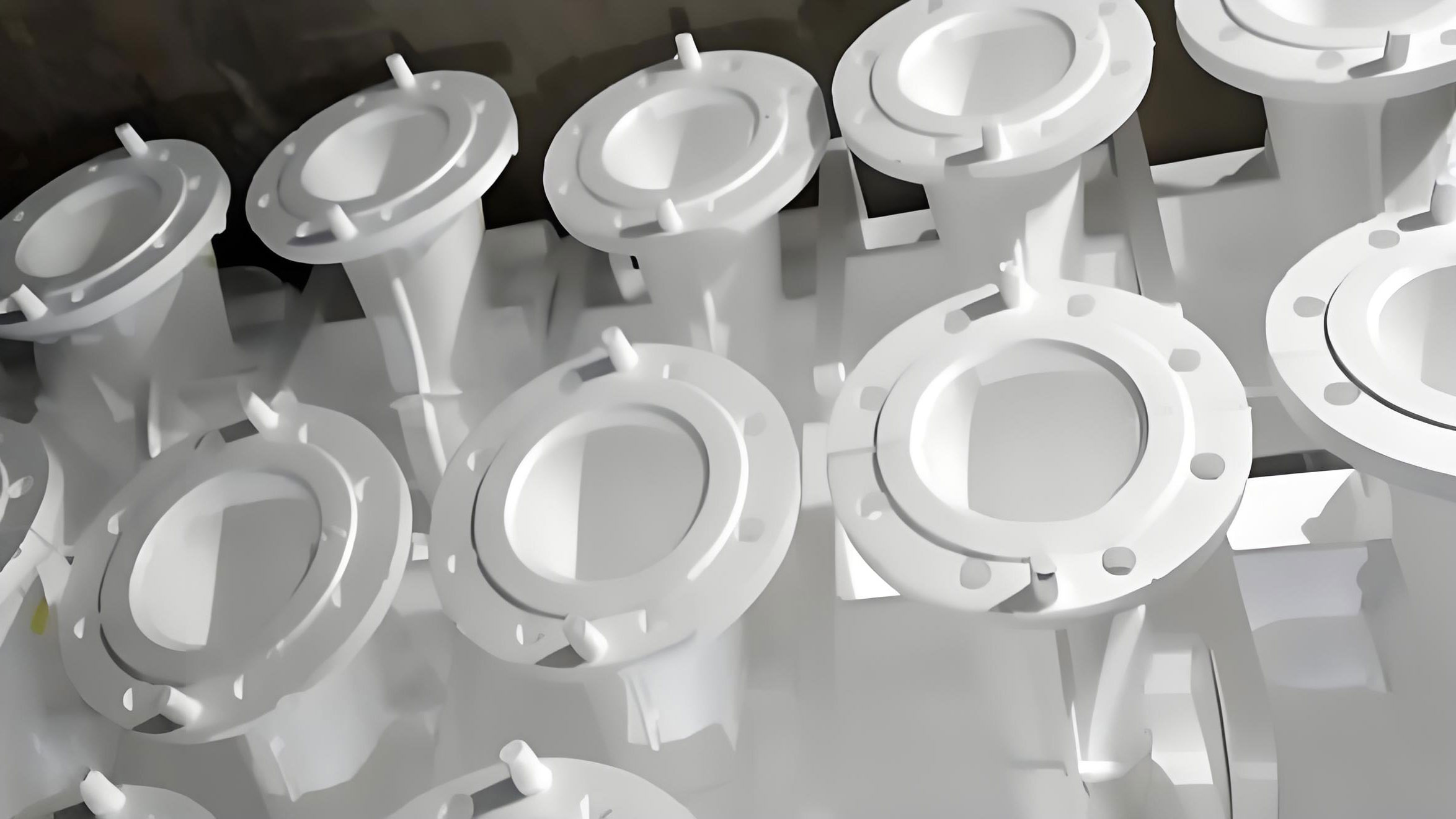
As a practitioner deeply involved in advanced casting technologies, my focus has been on refining the lost foam casting process for critical components. The production of ductile iron (QT450-10) reducer housings presents a classic yet challenging application for this method. While lost foam casting offers superior surface finish, dimensional accuracy, and high yield, it introduces unique defect mechanisms not commonly encountered in conventional sand casting. This article details a first-hand investigation into the root causes and innovative solutions for two persistent defects: inclusions and shrinkage cavities in the thick-section areas and end faces of these housings.
The component in question is a reducer housing weighing approximately 112 kg, with wall thicknesses varying from 14 mm to 54 mm. The geometry inherently creates pronounced thermal hot spots, making it susceptible to shrinkage-related defects. The standard lost foam casting setup involved a cluster of expandable polystyrene (EPS) or co-polymer patterns with a gating system designed for bottom filling. The standard process parameters are summarized below:
| Process Parameter | Value or Range |
|---|---|
| Pouring Temperature | 1370 – 1440 °C |
| Furnace Tapping Temperature | 1580 – 1600 °C |
| Molding Negative Pressure | -0.04 to -0.06 MPa |
| Negative Pressure Holding Time | 900 s |
| Base Pattern Material | Co-polymer (STMMA) |
The chemical composition of the QT450-10 iron used is critical for its mechanical properties but also influences casting behavior. The target composition is as follows:
| Element | Weight % (w%) |
|---|---|
| Carbon (C) | 3.5 – 4.0 |
| Silicon (Si) | 2.0 – 3.0 |
| Manganese (Mn) | ≤ 0.45 |
| Phosphorus (P) | ≤ 0.05 |
| Sulfur (S) | ≤ 0.025 |
| Magnesium (Mg) | 0.02 – 0.06 |
| Rare Earth (RE) | 0.015 – 0.040 |
Despite achieving satisfactory mechanical properties and nodularity (2-3 grade) in standard Y-blocks, initial production runs consistently revealed subsurface inclusions on the machined end faces and shrinkage cavities in the bolt boss regions, which are classic thermal junctions.
Mechanisms of Defect Formation in Lost Foam Casting
1. The Genesis of Inclusions
Inclusions in lost foam casting are predominantly carbonaceous, stemming from the incomplete degradation of the foam pattern. The choice of pattern material is paramount. Pure EPS and Expandable Polymethyl Methacrylate (EPMMA) have contrasting pyrolysis behaviors, as described by their simplified decomposition reactions:
For EPS:
$$ \text{C}_8\text{H}_8 (s) \rightarrow 8\text{C} (s) + 4\text{H}_2 (g) $$
For EPMMA:
$$ \text{C}_5\text{O}_2\text{H}_8 (s) \rightarrow 3\text{C} (s) + 2\text{CO}_2 (g) + 4\text{H}_2 (g) $$
Analyzing these stoichiometrically:
- EPS: Produces a high amount of solid carbon (8 mol C per mol of polymer) but a relatively lower gas volume (4 mol H₂).
- EPMMA: Generates more gas (6 mol total of CO₂ and H₂) but less solid carbon (3 mol C).
The co-polymer material (STMMA) is specifically engineered as a compromise, offering a balance between gas evolution and solid carbon residue. However, this compromise does not eliminate the problem. During pouring, the molten metal front rapidly vaporizes and pyrolyzes the foam. The resulting products—a complex mixture of gaseous, liquid, and solid hydrocarbons—must be transported through the coating and into the sand mold. If the kinetic conditions (temperature gradient, coating permeability, sand compaction, negative pressure) are not optimal, some of these solid carbonaceous products can become entrapped at the metal front, particularly at upward-facing surfaces where buoyancy forces are minimal. This leads to the formation of a carbon-rich, slag-like inclusion layer just beneath the casting skin. In our housings, this manifested as a discontinuous, friable layer on the top end face, with a measured maximum depth of 8 mm.
2. The Challenge of Shrinkage Cavities
Shrinkage defects in ductile iron, particularly in lost foam casting, arise from the inherent volume contraction during solidification, coupled with the graphite expansion phenomenon. The carbon equivalent (CE) of ductile iron is high, typically calculated as:
$$ CE = \%C + \frac{\%Si}{3} $$
For our composition, CE ranges from approximately 4.17 to 5.0, placing it in the hypereutectic region. While this promotes good fluidity and reduces shrinkage tendency compared to white iron, pronounced geometric hot spots can still overcome the compensating effect of graphite expansion. In lost foam casting, the insulating nature of the dry, unbonded sand and the foam decomposition gases can create a slower cooling environment compared to green sand, potentially exacerbating hot spot severity. The fundamental cause remains the inability to feed liquid metal to the last-solidifying region (the thermal center of a hot spot), resulting in a macroscopic cavity or a network of micro-shrinkage (porosity).
Innovative Defect Elimination Strategies and Validation
1. Practical Solution for End-Face Inclusions
Given that the carbon inclusion defect is intrinsic to the lost foam casting process mechanics, the strategy shifts from complete prevention to effective management. The goal is to ensure all inclusions are contained within a sacrificial volume of metal that is later removed by machining. Initial inspection and measurement confirmed the inclusion depth did not exceed 8 mm. The original process already included a 4 mm machining allowance on the end face. The solution was straightforward yet highly effective: increase the total machining allowance on the critical end face from 4 mm to 8 mm.
The validation was statistical. Tracking the machining yield (percentage of castings without scrap-defects after machining) before and after the change provided clear evidence:
| Condition | Machining Yield Rate | Observation |
|---|---|---|
| Original Process (4 mm allowance) | ~88% | Unacceptable scrap due to exposed inclusions. |
| Modified Process (8 mm allowance) | ~97.96% | Inclusions successfully removed with the extra stock. |
This simple modification transformed the scrap rate, proving that containment, rather than absolute elimination, is a viable and cost-effective strategy for carbon defects in lost foam casting.
2> Breakthrough Approaches for Shrinkage Elimination
Traditional methods to tackle hot spots—using risers or external chills—present significant drawbacks in lost foam casting. Risers drastically reduce the process yield and complicate the pattern cluster. Conventional solid chills are difficult to secure reliably within the loose, dry sand during vibration, risking displacement, mold wall collapse, or casting distortion. Our research led to the development and validation of two novel, process-sympathetic techniques: the Heat Dissipation Fin (HDF) process and the Flexible Chill process.
A. The Heat Dissipation Fin (HDF) Process
This is a conceptual leap in managing solidification within lost foam casting. Instead of adding mass (a riser) or a massive heat sink (a chill), we modify the geometry of the casting’s thermal environment to dramatically enhance localized heat extraction.
Principle & Procedure: Lightweight foam fins (e.g., 50 mm x 30 mm x 7 mm) are adhesively bonded directly onto the foam pattern at the identified geometric hot spot locations. The cluster is then coated, dried, and invested in sand as usual. During pouring and the critical solidification phase, the established negative pressure system plays a dual role: it stabilizes the mold and drives a controlled flow of ambient air.
This airflow enters from the top of the flask, percolates through the permeable sand, and is actively drawn past the casting and, most importantly, through the intricate network of sand grains surrounding the high-surface-area foam fins. The fins act as extended surfaces, effectively lowering the local modulus of the casting section. The air flow performs forced convection cooling, creating a pronounced “micro-channel” cooling effect. The fins and the adjacent sand become a highly efficient heat exchanger, effectively functioning as an internal chill and establishing a steep temperature gradient conducive to directional solidification away from the hot spot.
The governing heat transfer can be conceptually related to an enhanced cooling rate:
$$ \frac{dT}{dt}_{local} \propto \frac{h \cdot A_{eff} \cdot (T_{cast} – T_{air})}{\rho \cdot V \cdot C_p} $$
Where \( h \) is the effective convective heat transfer coefficient (enhanced by forced flow), \( A_{eff} \) is the greatly increased effective surface area due to the finned geometry, \( T_{cast} \) and \( T_{air} \) are the casting surface and air temperatures, \( \rho \) is density, \( V \) is volume, and \( C_p \) is specific heat. The HDF process maximizes \( A_{eff} \) and supports a higher effective \( h \).
Validation & Advantages: Applied to the bolt boss hot spots (12 fins total), the HDF process completely eliminated the shrinkage cavities, as verified by machining over 2,000 consecutive castings.
- High Process Yield: Adds negligible weight versus a riser.
- Simplicity: Easy to implement at the pattern assembly stage.
- Stability: Unlike physical chills, the bonded fins cannot shift during molding.
- Post-Processing: The fins burn out cleanly, leaving minimal finish work.
B. The Flexible Chill Process
For geometries where attaching external fins is impractical, an alternative was developed using a bulk material as a conformable chill.
Principle & Procedure: Small steel shot (e.g., 2-3 mm diameter) is placed into a cavity or against the pattern at the hot spot location. The area is then sealed with high-temperature resistant tape to prevent the shot from dispersing into the sand during flask vibration. Once the mold is compacted, the mass of steel shot acts as a high-heat-capacity, conformable chill, efficiently extracting heat from the critical region.
The cooling power is related to the chill’s heat capacity:
$$ Q_{chill} = m_{shot} \cdot C_{p, steel} \cdot (T_{fusion} – T_{initial}) $$
Where \( Q_{chill} \) is the total heat absorbed, \( m_{shot} \) is the mass of steel, \( C_{p, steel} \) is its specific heat, \( T_{fusion} \) is the solidus temperature of iron, and \( T_{initial} \) is the pre-packed chill temperature. The “flexible” nature ensures perfect contact with the complex pattern geometry, unlike a rigid chill.
Validation & Considerations: This method proved effective in preliminary trials. However, it requires a suitable recess or area on the pattern to contain the shot, and the optimal mass and packing density require careful development to avoid over-chilling or creating new stress points.
3. Synergistic Process Parameter Refinement
While the geometric solutions (HDF, Flexible Chill) are primary, stabilizing and optimizing the core lost foam casting parameters is essential for consistent results. A key focus was the application and control of negative pressure. Maintaining a stable, adequate negative pressure (-0.05 to -0.06 MPa) throughout pouring and the initial solidification phase is non-negotiable. It ensures:
- Pattern decomposition gases are promptly evacuated, reducing back-pressure and the risk of gas-related defects.
- Mold rigidity is maintained, preventing wall movement that can induce shrinkage.
- For the HDF process, it drives the essential convective cooling airflow.
A refined set of integrated process parameters is summarized below:
| Parameter Category | Optimized Value/Range | Rationale & Impact |
|---|---|---|
| Pattern Material | Co-polymer (STMMA) | Balances gas evolution & carbon residue for ductile iron. |
| Machining Allowance (End Face) | 8 mm minimum | Contains and allows removal of carbon inclusions. |
| Hot Spot Treatment | HDF or Flexible Chill | Forces directional solidification to eliminate shrinkage. |
| Pouring Temperature | 1380 – 1420 °C | Sufficient fluidity without excessive thermal stress. |
| Molding Negative Pressure | -0.05 to -0.06 MPa | Critical for mold stability, gas removal, and HDF cooling. |
| Pressure Hold Time | ≥ 900 s | Ensures complete solidification under pressure. |
Conclusion
This systematic investigation into the lost foam casting of ductile iron reducer housings demonstrates that the characteristic defects of the process can be successfully managed and eliminated through tailored engineering solutions. The carbonaceous inclusion defect, an inherent byproduct of foam pyrolysis, is effectively addressed not by futile attempts at complete prevention but by the practical strategy of incorporating sufficient machining allowance—a simple yet statistically validated fix that raised the machining yield to over 97%.
The more technically challenging issue of shrinkage cavities in thermal hot spots was solved through two innovative in-process cooling strategies developed specifically for the lost foam casting environment. The Heat Dissipation Fin (HDF) process represents a paradigm shift, using the process’s own negative pressure system to drive convective cooling through strategically placed foam extensions, thereby creating an internal chilling effect without the complexity of traditional methods. The Flexible Chill process offers an alternative for suitable geometries using steel shot as a high-capacity, conformable heat sink. Both methods maintain the high process yield that makes lost foam casting economically attractive while ensuring sound, dense castings in critical sections. The successful high-volume production validation of the HDF process, in particular, underscores its robustness and practicality as a new standard technique for enhancing the capabilities of lost foam casting for heavy-section ductile iron components.