
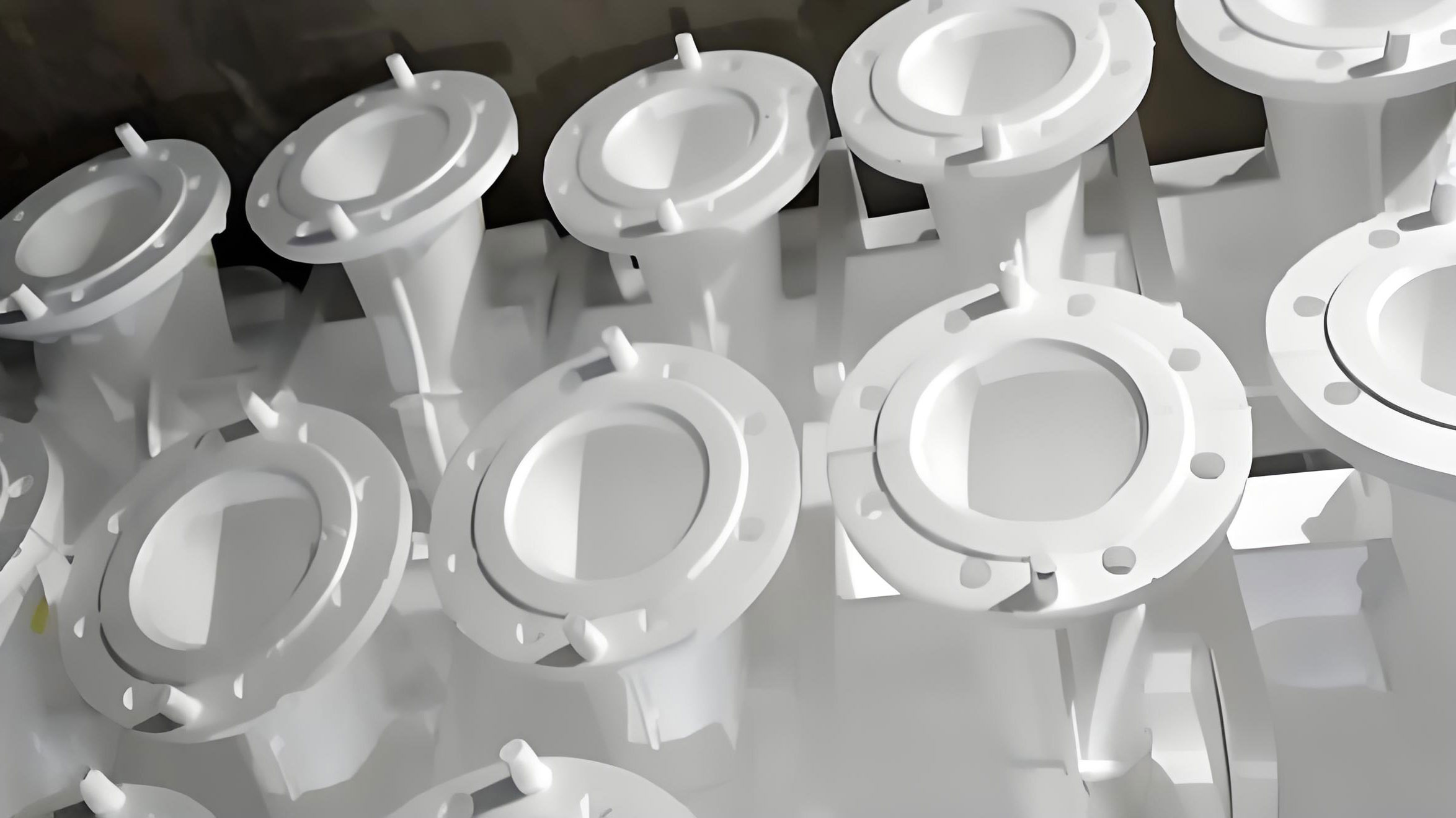
In my experience as a casting engineer, lost foam casting has emerged as a pivotal technology for producing complex components with superior surface finish, dimensional accuracy, and high yield. This process is particularly advantageous for ductile iron castings, such as reducer housings, which demand high strength, toughness, wear resistance, and vibration damping. The reducer housing in focus here weighs 112 kg, with wall thicknesses ranging from 14 mm to 54 mm, and features concentrated geometric hot spots. Given the capabilities of my foundry’s equipment and the part’s characteristics, lost foam casting was selected as the optimal manufacturing route.
The initial lost foam casting process for the ductile iron reducer housing, designated as QT450-10, involved a top-gating system. The pouring temperature was set between 1370 °C and 1440 °C, with a melting temperature of 1580–1600 °C. A vacuum pressure of -0.06 to -0.04 MPa was maintained during pouring, with a holding time of 900 s. Chemical composition requirements were strictly adhered to, as summarized in Table 1.
| Element | Range |
|---|---|
| C | 3.5–4.0 |
| Si | 2.0–3.0 |
| Mn | ≤ 0.45 |
| P | ≤ 0.05 |
| S | ≤ 0.025 |
| Mg | 0.02–0.06 |
| RE | 0.015–0.04 |
While Y-block specimens met the mechanical properties and nodularity (grades 2–3) per QT450-10 standards, trial production via lost foam casting revealed significant defects: wrinkling on the end faces and shrinkage porosity in geometric hot spots. These issues persisted in small-batch runs, indicating a need for process optimization. The root causes were investigated from the perspectives of pattern material behavior and solidification dynamics inherent to lost foam casting.
In lost foam casting, the foam pattern—typically made of copolymer resins balancing EPS and EPMMA—decomposes upon contact with molten metal, generating gaseous, liquid, and solid pyrolysis products. The transport and interaction of these products with the advancing metal front are critical. Wrinkling defects, manifesting as orange-peel-like surfaces, often occur at the last-filled regions or “cold zones” of the casting, such as top surfaces, vertical sidewalls, or dead corners. This is intrinsically linked to carbon defects due to the high carbon content (3.5–3.8%) in ductile iron and the residual carbon from pattern decomposition.
For the reducer housing, the original top-gating system effectively created a mid-bottom gating scenario. The molten iron entered from the top, bypassed the thick upper section, and used the cavity itself as a runner, leading to turbulent filling. This turbulence caused the initial cooler metal and insufficiently vaporized pattern residues to accumulate in the thick upper and side regions, forming cold zones and subsequent wrinkles. The filling behavior can be modeled using fluid dynamics principles. The Reynolds number (Re) for flow in lost foam casting can be expressed as:
$$ Re = \frac{\rho v D}{\mu} $$
where $\rho$ is the iron density, $v$ is the flow velocity, $D$ is the hydraulic diameter, and $\mu$ is the dynamic viscosity. Turbulent flow (Re > 4000) promotes defect formation. In the original design, the velocity $v$ was high due to the direct top entry, leading to Re values conducive to wrinkles.
Shrinkage porosity, on the other hand, stemmed from inadequate feeding during solidification. Ductile iron experiences liquid shrinkage and graphite expansion, but in geometric hot spots—like the thick sections around bolt holes—the local modulus (volume-to-surface-area ratio) is high, causing delayed solidification and insufficient liquid metal compensation. The local modulus $M$ is defined as:
$$ M = \frac{V}{A} $$
where $V$ is the volume of the hot spot and $A$ is its surface area. Higher $M$ values increase shrinkage tendency. In lost foam casting, the vacuum environment affects heat transfer, but without external aids, hot spots remain problematic.
To address wrinkling, I redesigned the gating system from top-gating to a bottom-gating configuration. This promotes laminar flow, with metal rising steadily from the bottom, ensuring that cooler metal and pyrolysis products are pushed to the top machining allowance. Theoretical calculations guided the new design. The pouring time $t$ is estimated based on casting weight $W$ (112 kg) and empirical factors. A common formula for lost foam casting is:
$$ t = k \sqrt{W} $$
where $k$ is a coefficient (typically 1.5–2.5 for ductile iron). Using $k = 2.0$, we get:
$$ t = 2.0 \sqrt{112} \approx 21.2 \text{ s} $$
This aligns with the original calculation of 24 s. The effective pressure head $H_p$ for bottom gating is calculated considering the height difference. For a cope height $H_0$ of 480 mm and a casting height $C$ of 200 mm, the average pressure head is:
$$ H_p = H_0 – \frac{C}{2} = 480 – \frac{200}{2} = 380 \text{ mm} = 38 \text{ cm} $$
The minimum ingate cross-sectional area $A_g$ required to ensure proper filling is given by:
$$ A_g = \frac{W}{0.31 \cdot t \cdot \rho \cdot \sqrt{H_p}} $$
Assuming $\rho = 7.0 \text{ g/cm}^3$ for ductile iron, and converting $W$ to grams (112,000 g):
$$ A_g = \frac{112000}{0.31 \times 21.2 \times 7.0 \times \sqrt{38}} \approx 3.8 \text{ cm}^2 $$
However, for lost foam casting, ingate areas are often enlarged to accommodate pattern decomposition gases. Based on experience, I selected a central sprue with four ingates, each measuring 70 mm × 40 mm, providing a total area of 11.2–12.8 cm². This ensures smooth filling. The new gating system eliminated turbulence, as verified by batch production of 2000 housings, all showing wrinkle-free surfaces.
For shrinkage porosity, traditional methods like risers or chills are less ideal in lost foam casting. Risers reduce yield, and chills may dislodge during molding or cause distortions. Instead, I developed a novel heat dissipation process specific to lost foam casting. This involves attaching foam “heat sinks” to the geometric hot spots on the pattern. These sinks, with dimensions such as 50 mm × 30 mm × 7 mm, increase the surface area $A$ locally, thereby reducing the modulus $M$. During pouring and solidification, the continuous vacuum draw in lost foam casting pulls ambient air through the sand, creating a micro-channel flow around the casting and sinks. This enhances heat extraction, acting as an effective chill. The heat transfer rate $Q$ can be approximated by:
$$ Q = h \cdot A \cdot \Delta T $$
where $h$ is the convective heat transfer coefficient, $A$ is the enhanced surface area, and $\Delta T$ is the temperature difference. By adding 12 heat sinks to bolt hole regions, the local modulus decreased significantly, promoting directional solidification. Batch trials confirmed the elimination of shrinkage pores in these areas.
The effectiveness of the heat dissipation process in lost foam casting is further highlighted by comparative data. Table 2 summarizes key parameters before and after optimization.
| Parameter | Original Process | Optimized Process |
|---|---|---|
| Gating System | Top-gating (turbulent) | Bottom-gating (laminar) |
| Ingate Total Area | Not specified | 11.2–12.8 cm² |
| Heat Dissipation Aids | None | Foam heat sinks (12 pieces) |
| Wrinkling Defect Rate | High (batch occurrence) | 0% (2000 pieces) |
| Shrinkage Porosity Rate | High in hot spots | 0% in bolt holes (2000 pieces) |
| Process Yield | Lower due to defects | High (minimal scrap) |
The success of these optimizations underscores the adaptability of lost foam casting. For wrinkling, the key was controlling fluid dynamics. The dimensionless number governing flow stability in lost foam casting can be extended to include pattern decomposition effects. A modified Reynolds number $Re’$ might be proposed:
$$ Re’ = \frac{\rho v D}{\mu + \mu_g} $$
where $\mu_g$ represents an effective viscosity due to gas evolution from the foam. Bottom gating reduces $v$, keeping $Re’$ low. For shrinkage, the heat dissipation process leverages the inherent vacuum of lost foam casting to actively cool hot spots. The temperature gradient $\nabla T$ achieved with heat sinks can be estimated using Fourier’s law in one dimension:
$$ q = -k \frac{dT}{dx} $$
where $q$ is the heat flux, $k$ is the thermal conductivity of the sand-metal interface, and $\frac{dT}{dx}$ is the temperature gradient. The sinks increase $\frac{dT}{dx}$ locally, accelerating solidification.
Further considerations in lost foam casting include pattern material selection. Copolymer patterns, as used here, balance gas generation and carbon residue, but for ductile iron, even small variations can cause defects. The gas evolution rate $G$ during decomposition follows an Arrhenius-type equation:
$$ G = A e^{-E_a/(RT)} $$
where $A$ is a pre-exponential factor, $E_a$ is activation energy, $R$ is the gas constant, and $T$ is temperature. In lost foam casting, controlling $T$ via pouring temperature is crucial; too low leads to incomplete decomposition and wrinkles, too high exacerbates shrinkage. The optimal range of 1370–1440 °C was maintained.
Vacuum pressure also plays a role. In lost foam casting, the vacuum removes decomposition products and enhances cooling. The pressure gradient $\nabla P$ affects gas flow. For a vacuum of -0.05 MPa, the flow velocity of air through the sand $v_s$ can be derived from Darcy’s law:
$$ v_s = \frac{K}{\mu} \nabla P $$
where $K$ is the permeability of the sand. Higher $v_s$ improves heat removal, aiding the heat sink process.
In conclusion, through systematic optimization of lost foam casting parameters, I resolved both wrinkling and shrinkage defects in ductile iron reducer housings. The shift to bottom gating eliminated turbulence-induced wrinkles, while the innovative heat dissipation process mitigated shrinkage porosity without compromising yield or simplicity. This study highlights the potential of lost foam casting for high-integrity ductile iron components when coupled with tailored fluid flow and thermal management strategies. Future work could explore numerical simulation of these phenomena to further refine lost foam casting processes for other complex geometries.
The lost foam casting process, with its unique advantages, continues to evolve. The integration of heat dissipation techniques opens new avenues for defect control. As I reflect on this project, the interplay between pattern decomposition, metal flow, and solidification in lost foam casting remains a rich area for innovation. By leveraging fundamental principles and practical adjustments, lost foam casting can achieve defect-free production even for challenging materials like ductile iron.