
As an engineer deeply involved in the advancement of foundry processes, I have dedicated significant effort to improving the efficiency and quality of lost foam casting. This innovative casting method, where a foam pattern is vaporized by molten metal to form a casting, has revolutionized the industry due to its ability to produce complex shapes with minimal post-processing. However, the process is not without challenges, particularly in the coating and drying stages. In lost foam casting, the foam pattern must be uniformly coated with a refractory slurry—often referred to as flow coating—and then thoroughly dried before molding. Any mishandling during these steps can lead to pattern deformation, coating defects, and ultimately, poor casting quality. Through my experiences, I have identified critical inefficiencies in traditional methods and developed a specialized tooling system to address them. This article delves into the design, application, and benefits of this tooling, emphasizing how it enhances the lost foam casting process by minimizing external forces on the foam pattern, thereby ensuring higher yield rates and operational safety.
The lost foam casting process begins with the creation of a foam pattern that mimics the final casting geometry. This pattern is then coated with a refractory material, which serves multiple essential functions: it prevents direct contact between the molten metal and the molding sand, thereby improving surface finish; it strengthens the fragile foam to withstand handling; and it facilitates the escape of gases generated during pouring through its permeable structure. The coating process, typically involving flow coating or brushing, must be meticulously controlled. As per industry standards, the coating is applied in multiple layers—usually two to three—with each layer requiring complete drying before the next application. This is crucial because an inadequately dried coating can lead to defects such as gas porosity, slag inclusions, or even violent reactions during pouring due to residual moisture. The ideal coating thickness is around 1 mm, a balance between preventing sand burn-on and maintaining sufficient gas permeability. In traditional lost foam casting setups, operators manually flip and rotate the foam pattern during coating, which not only increases labor intensity but also exposes the pattern to bending and torsional stresses. Moreover, after coating, the added weight of the slurry makes handling even more precarious, often resulting in pattern distortion. These issues underscore the need for a more refined approach to the coating and drying phases in lost foam casting.
To overcome these limitations, I designed a tooling system that fundamentally alters how foam patterns are handled during flow coating and drying. The core principle is to isolate the foam pattern from direct external forces by mounting it on a dedicated fixture. This system comprises several key components: a coating tank, a support frame, and a planar grid platform. The coating tank holds the refractory slurry and captures excess material during flow coating. The support frame is securely attached to the tank’s edges, featuring pivoting mechanisms that allow controlled tilting. The planar grid platform, made from lightweight alloy tubing for ease of handling, serves as the carrier for the foam pattern. It is designed with a mesh-like structure to enable slurry drainage and includes adjustable, soft clamping blocks to hold the pattern in place without causing damage. The entire assembly ensures that all manipulations—tilting for coating, moving to drying ovens—are performed via the tooling, not by direct contact with the foam. This design philosophy directly addresses the deformation risks inherent in lost foam casting, as the tooling absorbs and dissipates operational forces.
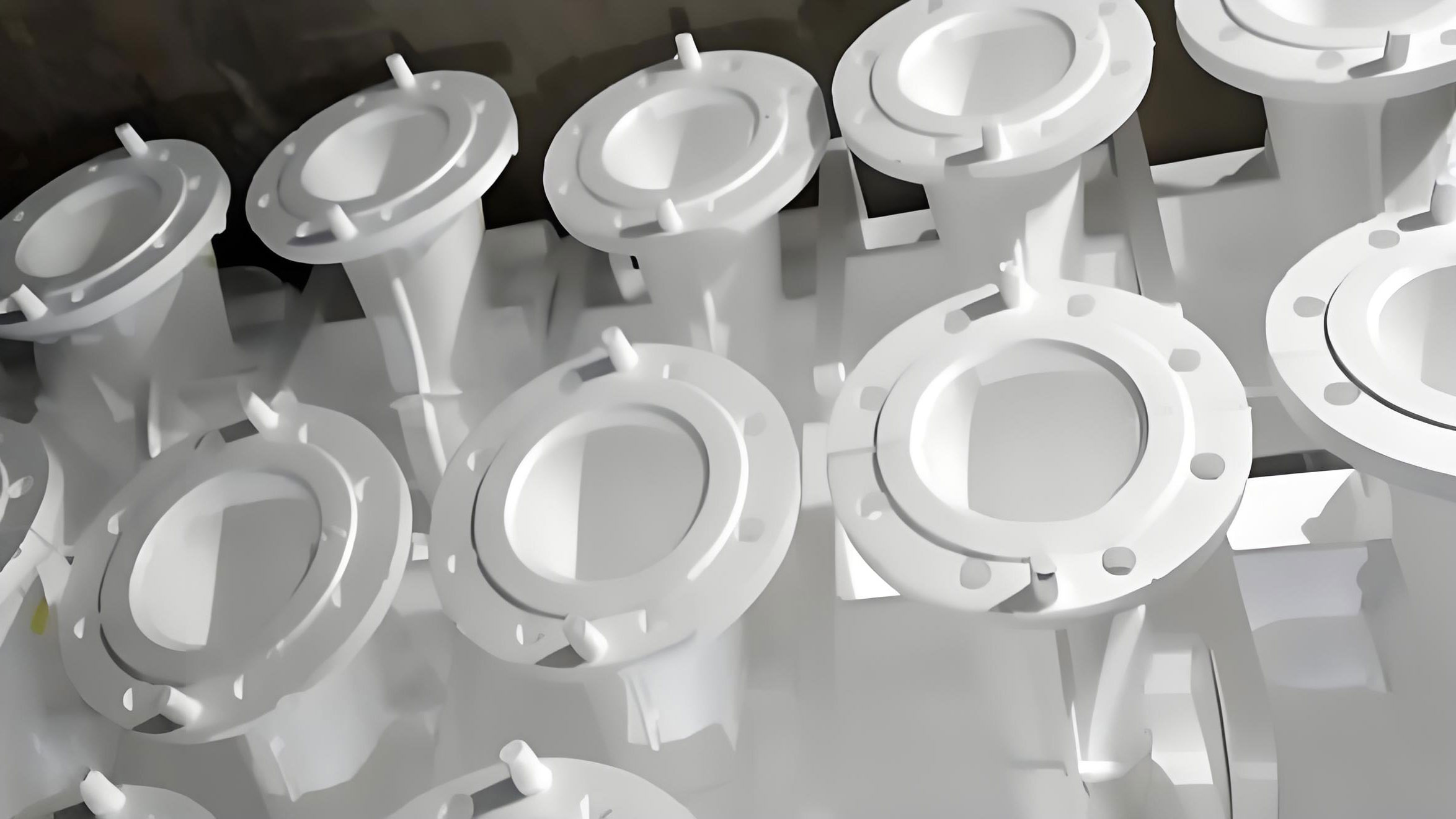
The operational methodology of this tooling in lost foam casting is straightforward yet highly effective. First, the foam pattern is positioned on the planar grid platform and secured using the clamping blocks to prevent shifting. The platform, with the pattern attached, is then placed onto the support frame above the coating tank. For flow coating, the platform is tilted leftward to an angle between 60° and 70° relative to the tank and locked in place. A hose with a spray nozzle is used to apply the slurry uniformly across the pattern’s surface. After coating one side, the platform is tilted rightward to the same angle for coating the opposite side. This dual-tilting action ensures complete coverage without requiring manual rotation of the pattern. Excess slurry drains through the grid openings into the tank for reuse, minimizing waste. Once coated, the entire assembly—platform and pattern—is detached from the support and transferred to a drying oven. Multiple patterns can be accommodated on a single platform based on size, and in the oven, platforms are stacked rigidly to optimize space without overlapping patterns, which prevents heat-induced deformation and ensures consistent drying. This process is repeated for subsequent coating layers, with each cycle maintaining pattern integrity. The tooling’s materials, such as hollow alloy tubes, are chosen for their low weight and rounded contact surfaces, further reducing the risk of pattern damage in lost foam casting.
The benefits of this tooling system in lost foam casting are quantifiable and significant. By eliminating direct handling, pattern deformation rates drop dramatically, leading to higher casting yields. Labor intensity is reduced as operators no longer need to manually flip heavy, slurry-laden patterns. The flow coating process becomes more consistent, ensuring uniform coating thickness—a critical factor in lost foam casting quality. To illustrate these advantages, consider the following table comparing traditional methods with the new tooling approach:
| Aspect | Traditional Method | Tooling-Based Method |
|---|---|---|
| Pattern Handling | Direct contact, manual flipping | Indirect via tooling, no direct contact |
| Coating Uniformity | Inconsistent due to manual application | High due to controlled tilting and spraying |
| Labor Intensity | High, requiring physical effort | Low, with ergonomic tooling operations |
| Pattern Deformation Risk | High, especially after coating | Low, as tooling absorbs forces |
| Drying Efficiency | Low, with potential stacking issues | High, with optimized oven space usage |
| Overall Yield in Lost Foam Casting | Variable, often compromised | Consistently improved |
Moreover, the coating thickness control in lost foam casting can be modeled mathematically. For a given slurry viscosity and application method, the final coating thickness \( t \) after \( n \) layers can be approximated by: $$ t = t_0 + (n-1) \cdot \Delta t $$ where \( t_0 \) is the thickness after the first layer and \( \Delta t \) is the incremental thickness per additional layer. In practice, for lost foam casting, \( t_0 \) is typically 0.3–0.4 mm and \( \Delta t \) is 0.2–0.3 mm, aiming for a total \( t \approx 1 \) mm after 2–3 layers. The tooling ensures that \( \Delta t \) remains consistent across all pattern surfaces, reducing variability. Another key formula relates to the drying time \( T_d \) in lost foam casting: $$ T_d = \frac{\rho \cdot c \cdot t^2}{k \cdot (T_o – T_a)} $$ where \( \rho \) is the coating density, \( c \) is specific heat capacity, \( k \) is thermal conductivity, \( T_o \) is oven temperature, and \( T_a \) is ambient temperature. The tooling’s grid structure enhances air circulation, effectively reducing \( T_d \) by increasing the heat transfer coefficient, which is crucial for speeding up the lost foam casting cycle.
In addition to the primary tooling design, several auxiliary considerations further optimize the lost foam casting process. For instance, the clamping blocks on the planar grid platform are made from flexible materials like silicone or rubber to accommodate thermal expansion during drying, preventing stress concentrations on the foam. The support frame’s pivoting mechanism incorporates locking pins with precision angles to ensure repeatable tilting, which is vital for batch consistency in lost foam casting. I also recommend integrating weight sensors into the tooling to monitor slurry pickup during coating, allowing for real-time adjustments. This can be expressed as: $$ W_s = A_p \cdot t \cdot \rho_s $$ where \( W_s \) is the slurry weight, \( A_p \) is the pattern surface area, \( t \) is coating thickness, and \( \rho_s \) is slurry density. By tracking \( W_s \), operators can verify coating uniformity without destructive testing. Furthermore, the tooling system is scalable; for large-scale lost foam casting production, multiple units can be synchronized on a conveyor system, automating the flow coating and drying stages. This not only boosts throughput but also aligns with Industry 4.0 trends in smart foundries.
The impact of this tooling on lost foam casting extends beyond operational efficiency to environmental and economic benefits. By reducing pattern damage, material waste from defective castings is minimized, lowering overall resource consumption in lost foam casting. The closed-loop slurry drainage system in the coating tank cuts down on refractory material usage, contributing to cost savings. Additionally, the ergonomic design reduces worker fatigue and injury risks, fostering a safer workplace. To quantify these effects, consider the following table summarizing key performance indicators before and after tooling implementation in a typical lost foam casting facility:
| Performance Indicator | Before Tooling | After Tooling | Improvement |
|---|---|---|---|
| Pattern Rejection Rate (%) | 15–20 | 3–5 | ~75% reduction |
| Coating Material Usage (kg per casting) | 2.5 | 2.0 | 20% savings |
| Labor Hours per Batch | 8 | 5 | 37.5% reduction |
| Drying Time (hours) | 4 | 3 | 25% faster |
| Overall Energy Consumption | High due to rework | Lower, optimized processes | Significant decrease |
These improvements highlight how targeted tooling innovation can transform lost foam casting into a more sustainable and profitable endeavor. The mathematical relationship for economic benefit can be derived as: $$ C_{total} = C_m + C_l + C_e $$ where \( C_{total} \) is total cost per casting, \( C_m \) is material cost, \( C_l \) is labor cost, and \( C_e \) is energy cost. With the tooling, \( C_m \) and \( C_l \) decrease due to reduced waste and labor, while \( C_e \) drops from shorter drying cycles. Thus, the return on investment for the tooling in lost foam casting is rapid, often within a few production runs.
Looking forward, the principles behind this tooling system can be adapted to other stages of lost foam casting, such as pattern assembly or mold filling. For example, similar fixtures could be used to secure foam clusters during gluing, preventing misalignment. The success of this approach underscores a broader lesson in manufacturing: by decoupling delicate components from operational stresses through smart tooling, quality and efficiency can be simultaneously enhanced. In lost foam casting, where the foam pattern is the literal template for the final product, this is especially critical. I encourage foundries to embrace such innovations, as they pave the way for next-generation lost foam casting capabilities, including the production of larger and more intricate castings with fewer defects.
In conclusion, the development and implementation of specialized tooling for flow coating and drying in lost foam casting represent a significant leap forward in foundry technology. Through firsthand application, I have witnessed how this system mitigates pattern deformation, streamlines operations, and boosts yield rates. The tooling’s design—centered on indirect handling and controlled tilting—addresses the core vulnerabilities of traditional methods, making lost foam casting more reliable and cost-effective. As the industry continues to evolve, such innovations will be essential for maintaining competitiveness and meeting rising quality standards. I am confident that by integrating tools like these, manufacturers can unlock the full potential of lost foam casting, producing superior castings with greater consistency and efficiency.