
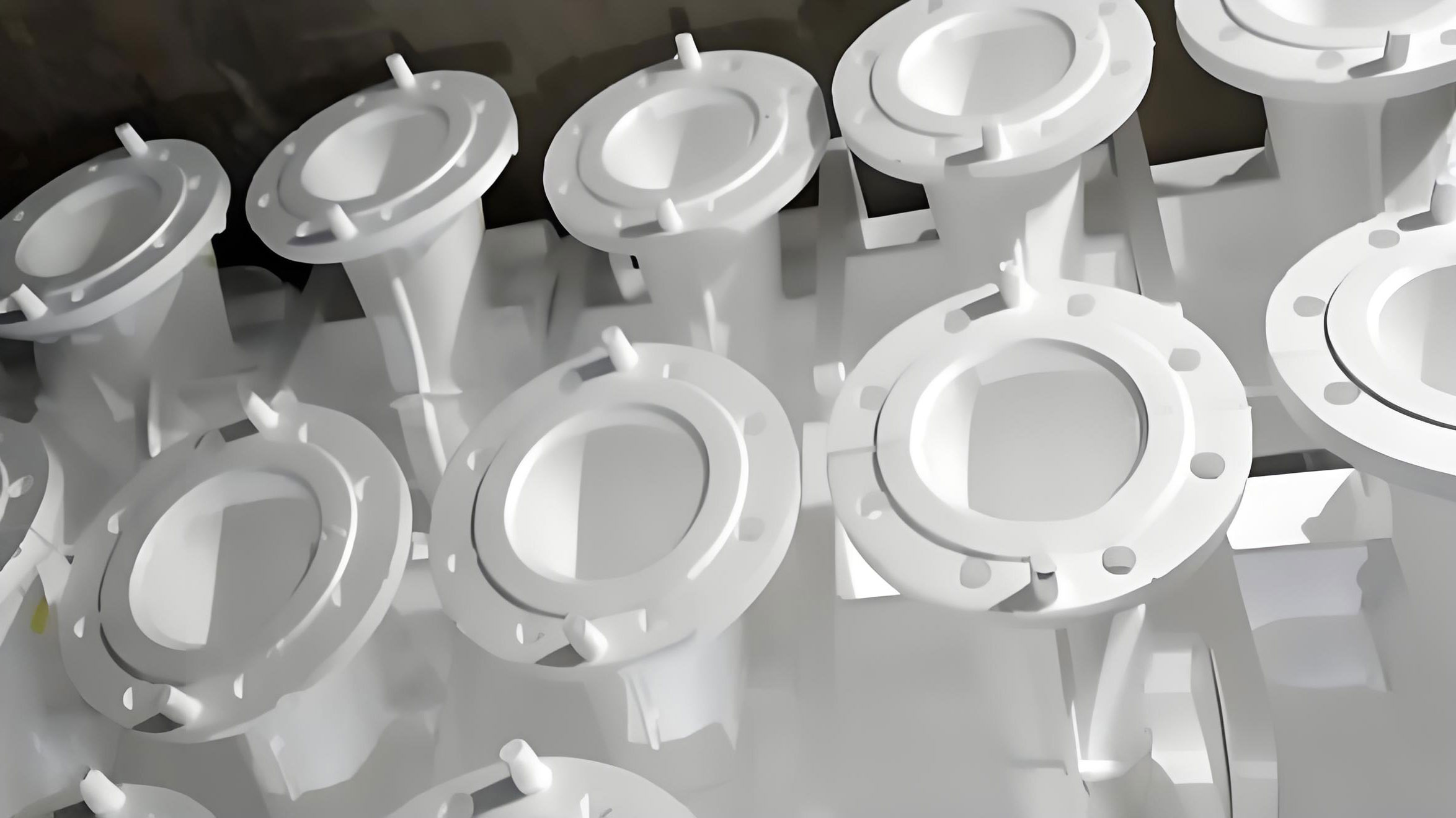
The advent of Lost Foam Casting (LFC) represents a paradigm shift in traditional foundry practices, often hailed as a “21st-century casting technology” and a “green engineering process within the foundry industry.” This innovative method involves creating a precise replica of the intended part from expandable polystyrene (EPS) foam. This pattern, after being coated with a refractory wash and dried, is placed in a flask surrounded by unbonded sand. The subsequent critical step is the compaction of this sand via a specialized vibration table. Finally, molten metal is poured, causing the foam pattern to vaporize and be replaced, resulting in a metal casting that mirrors the original foam shape. The efficacy of this entire process hinges profoundly on the performance of the vibration table. Insufficient sand compaction can lead to catastrophic defects such as mold wall collapse, expansion, metal penetration, and burn-on. Conversely, excessive or improper vibration can distort the delicate foam pattern, again compromising dimensional accuracy. Therefore, the design, control, and application of the vibration table are directly correlated with the compaction efficiency and, ultimately, the quality of the final casting.
The core function of a lost foam casting vibration table is to impart controlled mechanical oscillations to the flask assembly. Through the rotation of eccentric masses on vibratory motors, an oscillatory force, or excitation force, is generated. This force transmits kinetic energy to the granular sand bed. The resulting particle motion rearranges the sand grains, reducing voids and increasing packing density to form a rigid, self-supporting mold capable of withstanding the hydraulic pressure and thermal stresses of the poured metal. The key parameters governing this process are frequency (f, in Hz), amplitude (A, in mm), and the direction of vibration. These parameters must be optimized for different pattern geometries to ensure uniform filling of deep pockets, vertical walls, and horizontal undercuts without causing pattern deflection.
The fundamental dynamics of a vibratory system can be described by a simplified equation of motion for a forced vibration system. For a single-degree-of-freedom model representing the vibrating table and flask assembly, the equation is:
$$ m\ddot{x} + c\dot{x} + kx = F_0 \sin(\omega t) $$
where:
– \( m \) is the effective mass of the vibrating system (table, flask, sand, and pattern),
– \( c \) is the damping coefficient (primarily from the sand),
– \( k \) is the effective stiffness of the system,
– \( x \) is the displacement,
– \( F_0 \) is the magnitude of the excitation force from the vibratory motors,
– \( \omega \) is the angular frequency of excitation (\( \omega = 2\pi f \)),
– \( t \) is time.
The excitation force \( F_0 \) generated by a rotating eccentric mass is given by:
$$ F_0 = m_e \cdot e \cdot \omega^2 $$
where \( m_e \) is the eccentric mass and \( e \) is its eccentricity (the distance from the center of rotation to its center of mass). This shows that the激振力 increases with the square of the rotational speed, allowing significant compaction force to be generated with relatively small eccentric masses at high frequencies.
Domestic Research Landscape on Lost Foam Casting Vibration Tables
Research and development efforts within the domestic sphere have focused on various aspects of vibration table technology for lost foam casting, ranging from mechanical configurations to advanced control systems and simulation.
Dual-Motor Vibration Table Systems
A significant body of work has been dedicated to dual-motor configurations. The arrangement and rotational direction of the two motors fundamentally alter the vibration trajectory transmitted to the flask. Key operational modes have been identified:
- Co-rotational Mode: Both motors rotate in the same direction. Research indicates this mode generates an elliptical or linear vibration path that is predominantly horizontal. The distribution of acceleration amplitude along the vertical axis of the flask tends to be non-uniform, often described as a “V” shape. This makes it suitable for promoting horizontal sand flow and filling lateral cavities in the foam pattern.
- Counter-rotational Mode: The motors rotate in opposite directions. This mode is engineered to produce a primarily vertical linear vibration. Experiments show a more uniform distribution of acceleration and amplitude along the vertical axis, which is advantageous for the compaction of sand in vertical directions and for ensuring consistent density around vertically-oriented pattern features.
- Single-Motor Operation: Operating only one motor creates an inclined vibration vector. This can be useful for specific directional filling needs but offers less control than dual-motor setups.
The control of these modes is critical for process flexibility. Advanced control system designs have been implemented using Programmable Logic Controllers (PLCs) interfaced with frequency inverters. A typical system architecture allows an operator, via a human-machine interface (HMI), to select pre-programmed vibration recipes. The PLC then triggers specific combinations of contact closures to the frequency inverters, controlling motor start/stop, rotational speed (and thus frequency), and direction. This enables seamless switching between co-rotation, counter-rotation, and complex sequences combining both modes for multi-stage compaction cycles tailored to complex castings.
Further dynamical studies on dual-motor systems, often analyzed in the context of screening equipment which shares similar principles, reveal interesting non-linear behavior. For instance, a “complex-frequency” vibration mode with motors running at slightly different speeds can create a traveling wave effect on the table surface. This results in a non-uniform distribution of throw index and amplitude along the length of the table, which can be optimized to enhance material (sand) transport from the feed end to the discharge end while simultaneously improving packing.
Multi-Motor and Advanced Control Systems
For larger flasks or more complex compaction requirements, systems with more than two motors have been explored. One documented design incorporates six independently controllable vibratory motors, arranged in groups. A microcontroller-based system (e.g., an MCU-51 series) manages the actuation sequence and duration for each motor group. This allows for targeted, programmable vibration sequences. For example, motors under a deep pocket in the pattern can be activated first to initiate sand flow into that area, followed by a general full-table compaction cycle. Such systems add a layer of spatial and temporal control to the lost foam casting compaction process.
A crucial research direction involves the real-time determination of optimal vibration parameters. Instead of relying solely on empirical rules, one investigative approach utilizes dynamic pressure sensors embedded near the pattern surface. As the sand compacts, the pressure it exerts on the pattern wall changes. Monitoring this dynamic pressure provides a direct, real-time indicator of local compaction density. This feedback can theoretically be used to create closed-loop control systems for vibration tables, automatically terminating vibration once a target compaction state is achieved at critical points, thereby preventing both under-compaction and over-vibration.
The power of digital simulation is also being leveraged. Researchers create detailed 3D multi-body dynamics models of the vibration table, flask, and sand mass using software like ADAMS. By simulating the dynamic response under different motor configurations and parameters, they can predict the kinematic behavior (trajectories, accelerations) of the table surface before physical prototyping. This virtual prototyping significantly aids in the design and optimization of table structures and the pre-determination of suitable vibration parameters for specific lost foam casting applications.
Principles of Advanced Foreign Lost Foam Casting Vibration Table Technologies
International development of lost foam casting technology, particularly in regions like Japan and the United States, has a longer history, leading to commercially mature and often highly sophisticated vibration table systems. The underlying principles of some notable foreign designs offer valuable insights.
Japanese Vertical Circular Vibration Table
A prominent design originating from Japanese research employs a forced-drive mechanism to generate a circular vibration within the vertical plane. This is achieved by mounting two synchronized eccentric drive shafts, typically linked by gears or timing belts to ensure phase-locked operation. The key is to set the eccentric masses on these two shafts to rotate in the same direction but with a fixed phase difference (often 90 degrees). The combined force vectors from the two eccentrics result in a net excitation that causes the table to execute a circular, gyratory motion in a vertical plane. This type of motion is highly effective in promoting both vertical penetration and horizontal mobility of the sand grains simultaneously. It is reported to significantly reduce defects associated with uneven compaction, such as sand sintering in poorly filled areas and pattern deformation from unidirectional forces.
American High-Frequency, Low-Amplitude and Clamp-Type Vibration Tables
In the United States, two distinct philosophical approaches are evident. The first, exemplified by companies like GK, utilizes high-frequency, low-amplitude vibration. These tables often feature motors mounted exclusively to induce vertical oscillation. Interestingly, the flask is not rigidly clamped to the table. During operation, the vertical激振力 causes the flask to be momentarily “thrown” upward and then fall back onto the table. The compaction is achieved through a combination of the directed vibration and the repeated, slight impacts between the flask and the table. This method requires precise tuning of frequency and amplitude to control the throw height and ensure effective energy transfer.
The second, more advanced approach is embodied in clamp-type vibration tables, such as those from Vulcan. This design features a robust frame with pneumatic cylinders that actively clamp the flask securely to the vibration platform. The excitation is provided by pairs of specially designed vibratory motors mounted on the sides of the frame. The distinguishing feature of these motors is an integrated adjustable eccentric weight system. By mechanically adjusting the eccentric angle of the weights relative to each other on the motor shaft, the operator can continuously vary the nature of the output force vector.
This adjustability allows a single table to operate in multiple pure modes:
– Pure Horizontal Vibration
– Pure Vertical Vibration
– Elliptical or Circular Vibration (a combination of horizontal and vertical components)
The ability to select and fine-tune the vibration trajectory on-demand makes this type of lost foam casting vibration table exceptionally versatile. It can be optimized to tackle challenging pattern features: a strong horizontal component to drive sand into lateral undercuts, a strong vertical component for deep vertical fills, or a circular motion for overall uniform consolidation. This represents a significant leap in process control for lost foam casting.
The following table summarizes a comparison of the key vibration table types discussed:
| Table Type | Key Feature / Principle | Typical Vibration Trajectory | Primary Advantage | Typical Control Complexity |
|---|---|---|---|---|
| Basic Dual-Motor (Domestic) | Two standard vibratory motors, direction control. | Linear (Horizontal/Vertical) based on motor direction. | Good flexibility for basic patterns; cost-effective. | Moderate (PLC + Inverter for speed/direction). |
| Six-Motor Sequential (Domestic) | Multiple motor groups activated in sequence. | Spatially and temporally varied linear vibration. | Targeted compaction for complex, large patterns. | High (Microcontroller with sequence programming). |
| Japanese Vertical Circular | Phase-locked dual eccentric shafts. | Circular motion in the vertical plane. | Excellent simultaneous horizontal and vertical sand mobility. | Mechanical synchronization; fixed mode. |
| American High-Frequency | Unclamped flask, vertical throw. | Primarily vertical with impact component. | Simple mechanical design, effective for many shapes. | Moderate (Precise tuning of frequency/amplitude critical). |
| American Clamp-Type (Adjustable) | Flask clamped, motors with adjustable eccentricity. | Continuously variable from pure horizontal to pure vertical to elliptical. | Maximum versatility and process optimization for challenging geometries. | High (Mechanical adjustment + electronic control). |
Technical Discussion: Optimizing Vibration for Lost Foam Casting
The goal in lost foam casting vibration is to achieve a high and uniform bulk density (\(\rho_b\)) of the sand throughout the flask. This density is a function of the vibration parameters and the sand’s own properties. The relationship can be conceptually framed by looking at the sand’s behavior under cyclic loading.
During vibration, sand particles experience alternating shear and normal forces. The condition for particle rearrangement (and thus compaction) is often related to achieving a critical acceleration level. The “throw” condition, where particles briefly lose contact with each other or the pattern, is described by the throw index \(\Gamma\):
$$ \Gamma = \frac{A \omega^2}{g} = \frac{A (2\pi f)^2}{g} $$
where \(g\) is the acceleration due to gravity. For effective compaction in lost foam casting, \(\Gamma\) is typically maintained between 2 and 5. A value too low provides insufficient energy for particle movement; a value too high can cause excessive sand convection, pattern erosion, or even fluidization, which reduces density.
The optimal frequency and amplitude are interdependent. A useful empirical range for lost foam casting is:
– Frequency \((f)\): 30 Hz to 80 Hz (Higher frequencies are often used with lower amplitudes)
– Amplitude \((A)\): 0.2 mm to 1.5 mm
The required compaction time \((t_c)\) can be modeled as a function of achieving a target density. A simplified kinetic approach suggests an exponential approach to maximum density:
$$ \rho_b(t) = \rho_{max} – (\rho_{max} – \rho_0) e^{-K t} $$
where:
– \(\rho_b(t)\) is bulk density at time \(t\),
– \(\rho_{max}\) is the maximum achievable density under given conditions,
– \(\rho_0\) is the initial poured density,
– \(K\) is a compaction rate constant dependent on \(\Gamma\), vibration trajectory, and sand characteristics.
This highlights that while initial compaction is rapid, achieving the final few percentage points of density requires disproportionately longer time. Therefore, process optimization involves finding the shortest time \(t_c\) where \(\rho_b(t_c)\) meets the necessary threshold for the specific lost foam casting being produced.
Future Development Prospects and Strategic Directions
While foundational research in domestic circles is robust, bridging the gap to the level of integrated, commercially advanced systems seen abroad requires a focused, multi-pronged strategy. The future development of lost foam casting vibration technology should emphasize the following avenues:
1. Deepening Theoretical and Collaborative Research: There is a need to move beyond empirical optimization towards a fundamental, physics-based understanding of granular dynamics during the lost foam casting compaction process. This includes studying the interaction between sand particle size distribution, shape, moisture content, and the imposed vibration field. Strengthening partnerships between academic research institutions and foundry equipment manufacturers is crucial to translate theoretical models into practical hardware and control algorithms.
2. Fostering Innovation in the Industrial Base: A cultural shift towards valuing long-term technological investment over short-term cost savings is essential. Small, medium, and large enterprises involved in lost foam casting must recognize the vibration table not as a generic commodity but as a critical determinant of casting yield, quality, and profitability. Government and industry associations can catalyze this by co-funding demonstration projects, providing innovation grants, and establishing centers of excellence focused on advanced lost foam casting processes.
3. Integrating Advanced Simulation and Sensor-Based Control: The future lost foam casting vibration table will likely be a cyber-physical system. The path forward involves:
– Developing high-fidelity Discrete Element Method (DEM) simulations coupled with multi-body dynamics to virtually prototype sand flow and compaction for any given pattern.
– Employing sensor fusion (e.g., dynamic pressure, accelerometers, acoustic emissions) to provide real-time feedback on the compaction state.
– Creating expert system databases or machine learning models that, based on the 3D scan of a foam pattern, automatically recommend or directly execute an optimal vibration recipe (sequence, mode, frequency, amplitude, duration).
4. Mastering the Granular Physics of Lost Foam Casting: Targeted research should investigate the specific mechanisms of sand flow into complex cavities and undercuts under different vibration vectors. Understanding how to deliberately induce controlled sand convection to fill horizontal blind holes or upward-facing cavities without eroding the foam is a key challenge. This requires detailed experimental observation validated by sophisticated simulation.
5. Standardization and Knowledge Management: As expertise grows, developing standardized testing protocols for evaluating vibration table performance and sand compactability will be invaluable. Furthermore, creating and maintaining a shared knowledge base of successful vibration parameters for classes of castings (e.g., thin-wall, dense cores, tall vertical sections) can dramatically reduce process debugging time for new parts in the lost foam casting process.
Conclusion
The vibration table is undeniably the cornerstone of the lost foam casting process, transforming loose sand into a precision mold. Domestic research has established a strong foundation in understanding multi-motor dynamics and control sequencing. International technologies showcase the advantages of specialized mechanical designs like vertical circular motion and adjustable-eccentricity clamp systems that offer superior control over the vibration trajectory. The future of lost foam casting vibration technology lies in the convergence of advanced granular mechanics, sophisticated real-time sensing, predictive simulation, and intelligent control systems. By pursuing this integrated path, the next generation of vibration tables will provide unprecedented consistency, flexibility, and quality assurance, further solidifying lost foam casting’s position as a leading near-net-shape manufacturing technology for the 21st century. The evolution of this key equipment will directly enable the production of more complex, reliable, and cost-effective castings, driving the broader adoption of the lost foam casting method globally.