
In the landscape of modern abrasive tool manufacturing, the development of high-performance grinding wheels remains a focal point of research and industrial advancement. Traditional metal-bonded Cubic Boron Nitride (CBN) wheels are predominantly manufactured using powder metallurgy methods, with tin bronze serving as the primary binder. Despite its widespread use, this conventional approach presents significant challenges. The short duration of hot-pressing sintering often hinders the formation of robust metallurgical bonds, both between the binder components themselves and, crucially, between the binder matrix and the superabrasive grits. Consequently, the CBN grains are merely mechanically embedded and held within the metallic bond. This limitation prevents the full exploitation of the alloying elements’ potential within the matrix, resulting in compromised bond strength and inadequate grit retention. During the demanding conditions of grinding operations, this often leads to premature grit pull-out, reducing wheel life and performance. Furthermore, the powder metallurgy route can be associated with relatively high manufacturing costs.
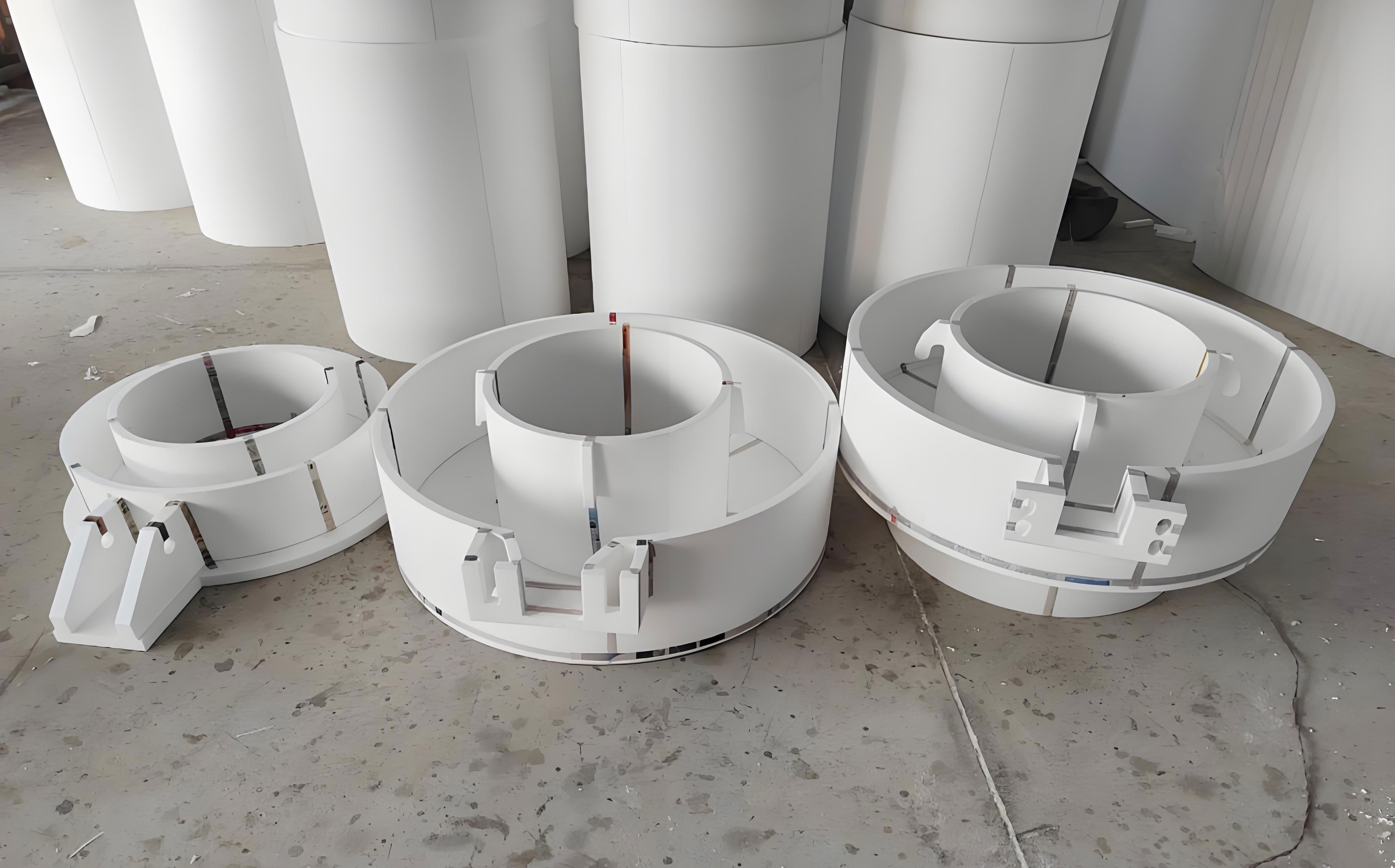
The search for alternative, more efficient manufacturing techniques has led to the exploration of casting-based methods. Among these, the Vacuum Lost Foam Casting (LFC) process has emerged as a particularly promising candidate. Characterized by its ability to produce high-precision castings with exceptional design flexibility, the absence of sand cores, and a clean production environment, lost foam casting is often hailed as a “green casting technology for the 21st century.” Its efficacy has been well-documented in numerous studies focusing on the fabrication of surface composite wear-resistant castings. A metal-bonded superabrasive grinding wheel can be conceptually viewed as a type of particle-reinforced metal matrix surface composite, where the abrasive grits act as the reinforcing phase within the metallic bond. This conceptual overlap suggests that the methodologies developed for creating surface composites via lost foam casting can be aptly adapted and leveraged for the manufacture of metal-bonded superabrasive wheels.
The choice of matrix material is paramount. Ductile iron, also known as nodular or spheroidal graphite iron, offers a compelling suite of properties. The spherical morphology of its graphite nodules minimizes the stress-concentration and crack-initiation effects typically associated with the flake graphite in gray cast iron. This allows ductile iron to retain the desirable foundry characteristics of cast iron—such as excellent castability, high wear resistance, good vibration damping, and low notch sensitivity—while simultaneously achieving mechanical properties (tensile strength, fatigue strength) comparable to medium-carbon steel, along with appreciable ductility and toughness. Its properties can be further enhanced through alloying and heat treatment. Employing a liquid-state forming technology like lost foam casting to produce a high-strength ductile iron-based CBN wheel presents distinct advantages. The natural shrinkage of the metal during solidification can create a compressive gripping force on the CBN grits within the abrasive layer, enhancing mechanical retention. Moreover, the intimate contact and potential interfacial reactions in the liquid state can promote stronger metallurgical bonding between the matrix and the grits compared to solid-state sintering. An added benefit is the potential for near-net-shape forming of both the wheel core and the abrasive layer in a single step. However, the as-cast surface finish and dimensional accuracy of a wheel produced by lost foam casting are generally inferior to those achieved by powder metallurgy, necessitating subsequent machining operations to meet final geometric and surface quality specifications. This study focuses on the integrated process, from design and simulation to casting and final machining, for fabricating ductile iron-based CBN grinding wheels using the lost foam casting technique.
Design of Casting Blank and Gating System
The target grinding wheel is a disc-shaped component with an outer abrasive ring serving as the working surface. The final part dimensions necessitate precise machining from a cast blank. The primary design objectives for the casting model are to ensure sound filling and solidification, facilitate the formation of a dense abrasive layer, and provide adequate reference surfaces for subsequent machining operations.
To meet the clamping and location requirements during machining—specifically for boring the central mounting hole—an integral false boss (or riser pad) is incorporated at the center of the wheel blank. This boss acts as a machining datum and also functions as a feed head to compensate for solidification shrinkage. Based on machining allowance and fixture design considerations, a boss height (H_boss) of 20 mm was deemed sufficient. The complete casting model, including the gating system, is shown schematically. The abrasive layer, containing the CBN grits within a foam pattern, surrounds the central core.
Given the simple disc geometry, a top-pouring gating system was designed, consisting of a pouring cup and a downsprue. The boss itself acts as the main feeder. For a casting mass estimated between 2-5 kg, standard foundry guidelines were used to determine the sprue dimensions. The sprue exit diameter (D_sprue) was set to 23 mm, with a pouring cup entrance diameter (D_cup) of 46 mm and a cup height (h_cup) of 30 mm. The calculated minimum required metallostatic pressure head was 9 mm.
A critical aspect of this process is the formation of the abrasive layer via a cast-in infiltration mechanism, distinct from conventional casting. Research on infiltration kinetics indicates that a higher metallostatic pressure promotes better infiltration quality. Therefore, maximizing the vertical distance (H) from the metal head in the pouring cup to the abrasive layer is beneficial. Considering the flask height (350 mm), the position of the vacuum pipe (230 mm from top), and a safety clearance of 50 mm to protect the vacuum line, the effective head height H was set in the range of 170-180 mm. This total head comprises the boss height, the sprue height above the boss, and the height of the abrasive layer itself.
Numerical Simulation and Analysis
To validate the design and optimize the process parameters, numerical simulation of the filling and solidification stages was conducted. The simulation parameters were based on preliminary experimental work and are summarized in the table below:
| Parameter | Value |
|---|---|
| Casting Vacuum Level | 60 kPa |
| Pouring Temperature | 1350 °C |
| Core Foam Pattern Density | 15 kg/m³ |
| Abrasive Layer Foam Pattern Density | 25 kg/m³ |
The simulation results for the solidification time field indicated a smooth filling process without defects like cold shuts or misruns. Solidification progressed rapidly from the outer abrasive layer inwards towards the central core, completing within approximately 500 seconds. The prediction of shrinkage porosity was particularly insightful. The simulation showed that shrinkage defects were concentrated within the central boss and the upper section of the sprue. Crucially, the predicted extent of this shrinkage zone was contained within the volume that would be removed during the subsequent machining of the wheel’s central bore. This means the final functional part of the wheel would be free from these inherent casting defects. The simulation confirmed the fundamental soundness of the designed gating and feeding system for the lost foam casting process.
Fabrication of Wheel Blanks with Different Matrix Microstructures
The goal was to produce two distinct types of ductile iron matrices: an Austempered Ductile Iron (ADI) or Austempered-Bainitic matrix, and a standard as-cast Pearlitic-Ferritic matrix. This was achieved by tailoring both the alloy composition and the post-casting cooling cycle.
Chemical Composition and Process Timing
To obtain an austempered-bainitic structure directly from the lost foam casting process, a combination of alloying and controlled cooling was employed. The aim was to suppress pearlite formation during cooling and then allow transformation in the bainitic region. The target chemical composition is given below:
| C | Si | Mn | Cr | Ni | Mo | Cu | S | P | Fe |
|---|---|---|---|---|---|---|---|---|---|
| 3.7 | 2.6 | 0.6 | 0.3 | 1.5 | 0.8 | 1.4 | <0.03 | <0.07 | Bal. |
A key process parameter is the shake-out time, which determines the temperature at which the casting is removed from the sand mold. Previous work indicated that for producing ADI via lost foam casting, a shake-out temperature around 900°C is effective. Simulation correlated this temperature with a shake-out time (t_shakeout) of approximately 850 seconds after pouring. This time was therefore used as the standard shake-out point.
Manufacturing Process and Cooling Strategies
The iron was melted in a medium-frequency induction furnace. The charge materials (steel scrap, pig iron) were melted first, followed by the addition of ferro-alloys (Fe-Mo, Fe-Cr, Fe-Mn) and silicon ferrosilicon for composition adjustment. The wheel pattern was assembled from a pre-formed abrasive layer foam segment and a core foam model. The assembled pattern was coated with a refractory wash, dried, and the coating process repeated three times to build a sufficient coating thickness. The coated pattern was then placed in a flask, backed with unbonded sand, and placed under vacuum awaiting pouring. The molten iron was treated with a nodularizing agent and an inoculant in the ladle at around 1550°C and poured into the mold at approximately 1350°C. Other casting parameters matched those used in the simulation.
Two different cooling paths were applied after the standardized 850-second shake-out to generate the different microstructures:
- Process I (Aimed at Austempered-Bainitic Matrix): Immediately after shake-out, the casting was rapidly cooled using forced air to about 450°C while simultaneously removing the sand and coating. It was then placed in an insulating material (aluminum silicate fiber blanket) to undergo an isothermal hold for 70 minutes, simulating an austempering treatment. Finally, it was air-cooled to room temperature.
- Process II (Aimed at Pearlitic-Ferritic Matrix): After shake-out, the casting was simply allowed to cool in ambient air to room temperature, representing a typical as-cast cooling cycle.
Microstructure and Mechanical Properties Analysis
Both processes yielded ductile iron with well-formed, spheroidal graphite. The nodularity was above 80%, and the graphite size was rated at 5-6 according to standard charts.
The matrix microstructures, however, were distinctly different. Process I produced a matrix consisting predominantly of lower bainite, with some upper bainite and retained austenite—characteristic of an austempered-bainitic structure. The alloying elements (Mn, Ni, Cr, Mo, Cu) shifted the continuous cooling transformation (CCT) diagram to the right, allowing the forced air cooling to bypass the pearlite nose. The subsequent isothermal hold in the bainitic temperature range facilitated the desired transformation.
Process II resulted in a typical as-cast microstructure of bull’s-eye ferrite surrounding the graphite nodules within a pearlitic matrix, i.e., a pearlitic-ferritic ductile iron. The slower air cooling rate allowed for transformation through the pearlite region.
The mechanical properties of the two materials were evaluated, with key results summarized below:
| Cooling Process | Matrix Microstructure | Hardness (HRC) | Transverse Rupture Strength (MPa) |
|---|---|---|---|
| Process I (Forced Air + Isothermal Hold) | Mainly Lower Bainite + Some Upper Bainite + Retained Austenite | 50.9 | 1596.2 |
| Process II (Air Cool) | Pearlite + Ferrite | 24.8 | 1376.8 |
Both materials exhibited high transverse rupture strength, suitable for a grinding wheel matrix. The most striking difference was in hardness. The austempered-bainitic iron (Process I) achieved a hardness more than double that of the pearlitic-ferritic iron (Process II). This is directly attributable to the hard, acicular lower bainitic structure. The hardness can be related to the microstructure through empirical relationships, often expressed in a general form for cast irons:
$$ HV \approx f_{α} \cdot HV_{α} + f_{P} \cdot HV_{P} + f_{B} \cdot HV_{B} + … $$
where \( f_{α}, f_{P}, f_{B} \) are the volume fractions of ferrite, pearlite, and bainite, and \( HV_{α}, HV_{P}, HV_{B} \) are their respective hardness contributions. The high \( HV_{B} \) value for lower bainite dominates the hardness in Process I.
Machining of the Cast Wheel Blank
The as-cast wheel blank, after removal of the gating system, possesses a rough surface finish and dimensional tolerances that are inadequate for direct use as a precision grinding wheel. The primary machining challenges are: 1) Achieving the final geometry and surface finish on the outer abrasive layer (which can only be done by dressing/conditioning, not conventional machining due to the CBN grits), and 2) Precisely machining the central mounting bore and the reference faces to ensure proper mounting and balance on a grinding machine spindle.
The central bore must be machined to a tight tolerance (e.g., \( \phi 31.75^{+0.016}_{0} \) mm) to fit precisely onto a wheel flange. Ensuring the accuracy and concentricity of this bore is the most critical aspect of the post-casting machining sequence.
Establishing Machining Datums and Process Planning
The machining strategy must establish reliable datums. The initial rough datum is the outer cylindrical surface of the abrasive layer. The first machining step is to turn the outer diameter of the central false boss, using the abrasive layer’s outer surface for initial chucking alignment. This ensures the boss’s OD is concentric with the abrasive layer, creating a precise cylindrical datum feature.
However, this boss OD is smaller than the abrasive layer OD, so it cannot be directly used in a standard chuck for the final boring operation. To solve this, a precision-machined bearing outer ring was utilized as an intermediate fixture. A standard tapered roller bearing outer ring (which is separable) was selected. Its external cylindrical surface was used as the primary location datum. Its internal tapered bore was partially machined to a precise cylindrical hole matching the diameter of the wheel’s turned boss. The wheel blank is assembled onto this boss, and the bearing-outer-ring assembly is then chucked by its OD, providing a highly accurate and rigid setup for machining the wheel’s final central bore.
The detailed machining process flow is outlined below:
| Step | Operation | Objective / Description |
|---|---|---|
| 1 | Deburring & High-Point Removal | Manually remove casting fins and high spots on the abrasive layer surface using a diamond file to prepare for initial clamping. |
| 2 | Turning of False Boss OD | Chuck on abrasive layer OD (rough datum). Turn the false boss outer diameter to a precise size \( \phi D_{boss} \) (e.g., \( \phi 110_{-0.015}^{0} \) mm) to create a machining datum. |
| 3 | Fixture Preparation | Machine a standard bearing outer ring: Use its own OD as datum to bore its inner tapered raceway into a precise cylindrical hole of size \( \phi D_{boss} + \text{fit} \). |
| 4 | Wheel Mounting on Fixture | Press-fit or assemble the wheel blank’s turned boss into the machined bearing ring fixture. |
| 5 | Facing & Preparatory Steps | Chuck the bearing ring by its OD (now the precision datum). Machine the wheel’s side faces and prepare for boring. |
| 6 | Boring of Central Hole | Using the same setup, machine the central bore. For highest accuracy and surface finish, a Low-Speed Wire Electrical Discharge Machining (LS-WEDM) process is employed. This non-contact method is ideal for achieving the tight tolerance (\( \phi 31.75^{+0.016}_{0} \) mm) and fine surface roughness (Ra 0.8 µm) required, unaffected by the hard or abrasive material. |
| 7 | Final Operations | Remove the wheel from the fixture. Cut off the remaining false boss material to final wheel width. The wheel is now ready for final abrasive layer dressing and balancing. |
The use of LS-WEDM for the final bore machining is critical. The accuracy is governed by the machine’s precision and the wire path, not by tool wear or cutting forces. The concentricity error (\( \epsilon \)) between the bore and the abrasive layer OD is minimized by this process chain and can be estimated as the root sum square of the individual setup errors:
$$ \epsilon \approx \sqrt{(\epsilon_{\text{turning}})^2 + (\epsilon_{\text{fit}})^2 + (\epsilon_{\text{WEDM}})^2 } $$
where \( \epsilon_{\text{turning}} \) is the error from turning the boss, \( \epsilon_{\text{fit}} \) is the assembly fit error between boss and bearing ring, and \( \epsilon_{\text{WEDM}} \) is the positioning error of the WEDM process. With careful execution, this total error can be kept well within the permissible runout tolerance for a precision grinding wheel.
Summary and Conclusions
This comprehensive study demonstrates the viability and outlines a complete methodology for manufacturing ductile iron-based CBN grinding wheels using the lost foam casting process. The integrated approach covers design, simulation, material engineering, and post-casting machining.
1. A cast wheel blank model was successfully designed, incorporating an integral central false boss. This boss serves the dual purpose of acting as a feeder to minimize shrinkage defects in the critical abrasive layer region and providing a necessary datum feature for downstream machining operations.
2. Numerical simulation of the lost foam casting process confirmed that the designed gating system promotes smooth filling. More importantly, it predicted that shrinkage porosity would be confined to the central boss area, which is subsequently removed during machining, ensuring the integrity of the final wheel.
3. By employing specific alloying compositions and controlled cooling strategies directly after the lost foam casting process, two distinct and high-performance ductile iron matrices were produced:
- A high-hardness (≈51 HRC) austempered-bainitic matrix achieved through a forced-air cool followed by an isothermal hold.
- A tougher, lower-hardness (≈25 HRC) pearlitic-ferritic matrix obtained through standard air cooling.
Both matrices exhibited high transverse rupture strength (>1375 MPa), making them suitable candidates for grinding wheel bodies.
4. A detailed machining process plan was developed to transform the rough casting into a precision grinding wheel. The key innovation involves using a precision-machined standard bearing outer ring as an intermediate fixture. This fixture allows the wheel blank to be located via its machined boss and then held by the bearing’s own perfect outer diameter, creating an ultra-precise datum system. The final central bore is machined using Low-Speed Wire EDM, capable of achieving the micron-level tolerances and fine surface finish required for dynamic balance and precise mounting on a grinding spindle.
In conclusion, the lost foam casting technique presents a compelling alternative to traditional powder metallurgy for manufacturing certain types of metal-bonded superabrasive tools. It offers potential benefits in terms of stronger grit bonding via solidification shrinkage, near-net-shape capability, and possibly lower cost for certain wheel geometries. The success of the process hinges on a holistic view that seamlessly integrates casting design, metallurgical control, and precision machining into a coherent manufacturing sequence. This study provides a foundational framework for such an integrated approach to producing high-performance cast iron-based grinding wheels.