
In contemporary stadium architecture, large-span cable network structures have emerged as a dominant trend, offering unparalleled design flexibility and structural efficiency. The cable clamp, serving as the principal load-transferring component within these networks, is subjected to immense and complex forces. Given their intricate geometries and stringent performance requirements, these clamps are predominantly manufactured as steel castings. The quality of these steel castings is paramount, directly influencing the structural integrity, safety, and longevity of the entire roof system. This article delves into the comprehensive quality control methodology for large, complex cast steel cable clamps, drawing upon practical engineering experience. The focus encompasses the entire lifecycle: from foundry工艺 and metallurgical specifications to non-destructive testing, welding procedures for dissimilar material joints, and full-scale validation of mechanical performance through slip resistance testing.
The structural system under consideration features a double-layer spoke-type cable-truss configuration. The roof, with a major axis span of 261.8 meters and a minor axis span of 224 meters, is supported by a network comprising 52 radial cables (with diameters of 75mm, 85mm, 105mm, and 120mm) and 16 circumferential cables (with diameters of 80mm and 110mm). All cables are domestically produced locked-coil strands. The cable clamps are categorized into circumferential cable clamps (104 pieces) and radial cable clamps (520 pieces), with a total weight exceeding 500 metric tons. The circumferential clamp, due to its larger size and more complex loading, will serve as the primary example for discussing the manufacturing and quality assurance processes. The designated material for these critical steel castings is G10MnMoV6-3+QT2, a high-strength cast steel grade.
The technical specifications for the steel castings are rigorous. The chemical composition and mechanical properties must conform to the European Standard EN 10293:2005 for “Steel castings for general engineering uses.” Prior to the production of actual structural clamps, prototype test blocks must be cast and evaluated according to EN 1559-2. Key mechanical property requirements, which can be expressed as formulae for clarity, include:
$$ \text{Yield Strength } (\sigma_y) \geq 380 \, \text{MPa} $$
$$ \text{Tensile Strength } (\sigma_u) = 500 – 650 \, \text{MPa} $$
$$ \text{Elongation } (A) \geq 18\% $$
$$ \text{Charpy Impact Energy at Room Temperature } (KV) \geq 60 \, \text{J} $$
Dimensional tolerances are classified based on nominal size: CT11 for dimensions >25mm and CT10 for dimensions ≤25mm. The cable groove surfaces, critical for grip, require a tighter tolerance of CT8 and a surface roughness (Ra) of 25 μm. Following machining and grit blasting to Sa 2.5, a robust corrosion protection system is applied, culminating with a polysiloxane topcoat. Importantly, the internal surface of the cable groove receives a 1 mm thick thermal-sprayed zinc coating to enhance the frictional grip on the cable.
Foundry Process for Steel Castings
For the large and geometrically complex circumferential cable clamps, sand casting was selected as the optimal manufacturing route due to its flexibility, suitability for low-to-medium volume production, and ability to handle large part sizes. The process flow is systematic:
- Pattern Making
- Molding and Core Making
- Melting and Pouring
- Shakeout and Cleaning
- Heat Treatment (Normalizing & Tempering)
- Riser Removal & Grinding
- Machining
- Inspection & Testing
- Surface Preparation & Coating
Process control during molding and pouring is critical. High-quality silica sand and alcohol-based coatings were used to achieve superior surface finish and prevent burn-on. The gating and risering system was meticulously designed following fundamental principles of sound casting: ensuring smooth, non-turbulent metal flow to avoid sand inclusion; facilitating directional solidification towards the risers to prevent shrinkage porosity; and providing adequate venting to eliminate gas entrapment. The control of pouring temperature and the rate of metal rise in the mold cavity are monitored parameters vital for quality.
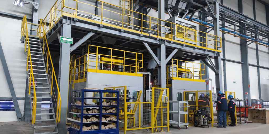
Heat treatment is a transformative step for the metallurgical properties of the steel castings. A normalizing and tempering (QT) cycle is employed. Normalizing refines the grain structure and enhances homogeneity, while tempering relieves internal stresses induced during casting and cooling, and optimizes the combination of strength and toughness. The final material designation, G10MnMoV6-3+QT2, explicitly indicates this quenched and tempered condition.
Material Verification and Non-Destructive Testing
Quality assurance is built on a multi-stage inspection regime. The initial step is the verification of material properties via separately cast test blocks. The results from the test blocks for the G10MnMoV6-3+QT2 steel castings confirmed compliance, as summarized below:
| Test Block ID | Yield Strength (MPa) | Tensile Strength (MPa) | Elongation (%) | Impact Energy, J (Avg.) |
|---|---|---|---|---|
| 1 | 485 | 635 | 18.9 | 68 |
| 2 | 475 | 625 | 19.0 | 65 |
| 3 | 492 | 642 | 19.3 | 65 |
| Specification | ≥380 | 500-650 | ≥18 | ≥60 |
The chemical composition was also verified to be within the specified limits, ensuring the correct alloying elements were present to achieve the desired hardenability and strength.
$$ \text{Carbon (C)} \leq 0.12\%,\quad \text{Manganese (Mn)} = 1.2-1.8\%,\quad \text{Molybdenum (Mo)} = 0.2-0.4\%,\quad \text{Vanadium (V)} = 0.05-0.1\% $$
Non-destructive testing (NDT) forms the backbone of quality control for the finished steel castings. Two primary methods are employed sequentially:
- Ultrasonic Testing (UT): Performed after rough machining to detect internal flaws such as shrinkage, porosity, or inclusions. Testing is conducted according to GB/T 7233.1-2009 (equivalent to ISO 4992-1), with acceptance criteria set at Quality Level 2.
- Magnetic Particle Testing (MT): Conducted on all accessible surfaces after final machining to reveal surface and near-surface discontinuities like cracks or cold shuts. Inspection follows GB/T 9444-2007 (equivalent to ISO 4986), also with Level 2 acceptance criteria.
Only after successful completion of all dimensional checks, NDT, and surface roughness verification do the steel castings proceed to coating.
Welding of Dissimilar Steel Joints
The circumferential cable clamp casting serves as a central node, requiring attachment points for other structural elements. In this case, forged ears or lugs made from high-strength low-alloy steel Q345GJC (with a thickness of 50mm) are welded onto the main casting body. This creates a dissimilar metal weld between the cast steel (G10MnMoV6-3) and the wrought steel (Q345GJC), presenting unique challenges in weldability and residual stress management.
A comprehensive welding procedure specification (WPS) was developed, qualified, and implemented. Key steps include:
1. Joint Preparation: A single-V groove with a 35° angle is machined into the Q345GJC plate. The groove face and adjacent areas (100mm wide) on both materials are cleaned to bare metal.
2. Preheating and Interpass Temperature Control: Given the substantial thickness of the casting (up to 130mm), controlled heat input is essential to prevent cracking. The carbon equivalent (Ceq) for both materials was calculated. A common formula is:
$$ C_{eq} = C + \frac{Mn}{6} + \frac{Cr + Mo + V}{5} + \frac{Ni + Cu}{15} $$
For these specific grades, the Ceq was approximately 0.39, indicating moderate hardenability and a need for preheat. A minimum preheat temperature of 120°C was mandated using flame heating. The interpass temperature was strictly maintained between 150°C and 200°C.
3. Welding Process and Parameters: Gas Metal Arc Welding (GMAW) with CO2 shielding gas was selected for its efficiency and deep penetration. The filler metal was a matching flux-cored wire, T492T1-1C1A. Welding parameters were tightly controlled as per the qualified WPS to manage heat input.
| Weld Pass | Current (A) | Voltage (V) | Travel Speed (cm/min) | Gas Flow (L/min) |
|---|---|---|---|---|
| Root | 180-260 | 25-30 | 25-45 | 15-20 |
| Fill | 220-320 | 25-38 | 25-45 | 15-20 |
| Cap | 220-280 | 25-38 | 25-45 | 15-20 |
4. Post-Weld Heat Treatment (PWHT) & Inspection: After welding, the joint was covered with insulating blankets to allow for slow, controlled cooling (post-heat) to mitigate the risk of hydrogen-induced delayed cracking. Ultrasonic testing was performed no less than 24 hours after welding completion to verify the integrity of the weld fusion zone and heat-affected zone (HAZ).
Full-Scale Anti-Slip Performance Validation
The fundamental function of a cable clamp is to grip the cable without slipping under extreme loads. Theoretical calculations of friction coefficients and clamping forces must be empirically validated. A full-scale anti-slip test was conducted to determine the actual slip resistance and the effective coefficient of friction (\(\mu\)) between the zinc-coated casting groove and the cable.
Test Setup: A cable clamp assembly (casting, pressure plate, high-strength bolts) was installed on a section of the actual locked-coil cable. Hydraulic jacks were used to apply tension to the cable, simulating in-service load. A separate hydraulic pusher system was mounted to apply a transverse force to the clamp, attempting to induce slippage relative to the cable. Instrumentation included load cells, long-stroke displacement transducers, and bolt tension sensors, all connected to a data acquisition system.
Test Procedure:
1. Bolts were torqued to a specified preload (e.g., 1000 N·m), and the resulting bolt tension was monitored until it stabilized, revealing the initial relaxation.
2. The cable was tensioned to 50% of its nominal breaking load and held. Bolt tension was again monitored until stable, capturing the relaxation under service load.
3. With the cable under constant tension, a transverse “push-out” force was applied to the clamp in incremental stages. The force and corresponding displacement were recorded until gross slippage occurred.
Results and Analysis: The test yielded several critical parameters:
– The torque coefficient (\(K\)) for the specific bolt/clamp interface was determined from the initial bolt tension data.
– The ultimate anti-slip load (\(F_{slip}\)) was recorded. In this instance, the tested capacity (429.7 kN minimum) significantly exceeded the design requirement (260 kN).
– The comprehensive coefficient of friction (\(\mu\)) for the system (incorporating the effects of the zinc coating, surface roughness, and clamping pressure) was calculated. The relationship is derived from the force balance at the point of slippage:
$$ F_{slip} = \mu \cdot N $$
where \(N\) is the total normal clamping force provided by the bolts. The tested \(\mu\) value was 0.31, validating the design assumptions for the steel castings‘ grip performance.
The slip force vs. displacement curve clearly showed an initial elastic phase, a period of micro-slip, and finally a pronounced non-linear increase leading to gross slippage, confirming the robustness of the design.
Conclusion
The successful deployment of large-span cable network structures is intrinsically linked to the performance of its critical nodes—the cable clamps. Manufacturing these components as high-integrity steel castings from grades like G10MnMoV6-3+QT2 provides the necessary combination of geometric freedom, high strength, and toughness. This article has detailed a holistic quality control framework that extends from the foundry floor to full-scale structural validation. Key to this framework are: a rigorously controlled sand-casting and heat treatment process; a comprehensive material verification and NDT protocol; a carefully managed welding procedure for dissimilar material attachments; and finally, empirical proof of performance through anti-slip testing. This multifaceted approach ensures that the steel castings meet not only the specified material standards but also their ultimate functional requirement: securely anchoring the cable network under all design loads. The methodologies and controls described serve as a validated reference for the engineering and quality assurance of critical steel castings in future complex structural applications.