
The evolution of railway transport towards higher speeds and heavier loads has placed unprecedented demands on braking systems. In regions where electrification is challenging, diesel locomotives remain crucial, and their performance, especially at speeds of 160 km/h, hinges on a reliable and robust braking solution. The limitations of traditional tread braking at such speeds necessitate the adoption of disc brake systems. This work details the comprehensive development process of a cast steel brake disc body designed specifically for 160 km/h diesel locomotives, from initial conceptual design and thermal analysis to material selection, manufacturing, rigorous testing, and final service validation.
Structural Design Philosophy
The foundation of an effective brake disc lies in its structural design, which must balance mechanical strength, efficient heat dissipation, and reliable mounting. Based on the bogie configuration, a wheel-mounted disc design was adopted. The disc body is split into two identical halves. Key dimensions are an outer diameter of 1060 mm, an inner diameter of 790 mm, and a total thickness of 52 mm, with a 20 mm thick friction ring.
The cooling surfaces feature an array of radial fins. The mounting strategy is critical for performance and longevity. A combination of positioning keys and bolts is used: six positioning pins pass through the wheel web, with their ends engaging keyways in the disc body to provide positive location and transmit braking torque, thereby shielding the bolts from shear forces. Eighteen bolts then secure the disc to the wheel web. Insulating sleeves are placed between the bolts/nuts and the disc body. This serves a dual purpose: it minimizes heat transfer from the hot disc to the fasteners, and it increases the effective length of the bolt, enhancing its elastic resilience to thermal cycling. This design offers several advantages: excellent ventilation from the evenly spaced fins, freedom for thermal expansion in most areas, and a clear separation of functions where positioning keys handle torque transmission and bolts handle clamping force.
Thermal Load Simulation and Verification
A brake disc’s primary function is to convert kinetic energy into heat and dissipate it effectively. Validating its thermal capacity under extreme conditions is paramount. The design must withstand the thermal load from two consecutive emergency stops from the maximum operating speed. The simulation parameters are summarized below:
| Parameter | Value |
|---|---|
| Initial Temperature | 70 °C |
| Maximum Axle Load | 23 t |
| Wheel Diameter (New/Half-worn/Fully-worn) | 1250 / 1200 / 1150 mm |
| Maximum Test Speed | 180 km/h |
| Emergency Deceleration | 0.95 m/s² |
| Acceleration between stops | 0.4 m/s² |
A finite element model was constructed in ABAQUS software. Due to the 60° rotational symmetry of the disc, one-sixth of the geometry was modeled to reduce computational cost. The material properties for the specific steel castings alloy, including temperature-dependent specific heat capacity and thermal conductivity, were assigned. The simulation consisted of four sequential steps: first emergency brake, acceleration to top speed, second emergency brake, and cooling.
The key load is the heat flux applied to the friction surfaces. The instantaneous heat flux per unit area is derived from the braking power and is a function of time:
$$ q(t) = \frac{\eta M a (v_0 – a t)}{S} $$
Where:
$q(t)$ = Instantaneous heat flux density (W/m²)
$\eta$ = Heat absorption efficiency (typically 0.9 for the disc)
$M$ = Axle mass (kg)
$a$ = Deceleration (m/s²)
$v_0$ = Initial speed (m/s)
$t$ = Time (s)
$S$ = Total friction surface area of the disc (m²)
This equation shows the heat flux is highest at the onset of braking and decreases linearly to zero when the train stops. This time-varying load was applied in the model using a tabular amplitude curve.
The simulation results were successful. The temperature history of the hottest point on the disc surface showed a peak of 265°C during the first stop and a higher peak of 394°C during the second stop, occurring after approximately 195 seconds of the simulation timeline. These maximum temperatures were well within the acceptable thermal limit for this class of steel castings, confirming the design’s adequacy for the intended duty cycle.
Material Selection for High-Performance Steel Castings
The demanding service environment requires the disc material to possess a rare combination of high strength, toughness, thermal conductivity, thermal fatigue resistance, and wear resistance. Low-alloy quenched and tempered steels have proven to be excellent candidates for such steel castings. The specific chemical composition is meticulously controlled to achieve the desired microstructure and properties. Elements like Chromium (Cr) and Nickel (Ni) enhance hardenability, wear resistance, and resistance to thermal cracking. Silicon (Si) and Aluminum (Al) contribute to the formation of stable oxides and can improve strength at elevated temperatures. Manganese (Mn) increases hardenability and helps refine the microstructure.
Impurity control is especially critical. Low levels of Hydrogen (H), Oxygen (O), and Nitrogen (N), as well as non-metallic inclusions, are essential to prevent internal defects and ensure integrity. Therefore, the steel melt undergoes secondary refining in a ladle furnace to achieve precise chemical composition and high cleanliness before the steel castings process.
The targeted mechanical properties for the finished steel castings are as follows:
| Property | Minimum Requirement |
|---|---|
| Tensile Strength | ≥ 1050 MPa |
| Yield Strength (Rp0.2) | ≥ 900 MPa |
| Elongation | ≥ 8.0 % |
| Impact Energy (20°C, KV2) | ≥ 27 J |
| Hardness (HBW) | ≥ 290 |
Manufacturing Process and Quality Control
The manufacturing of these high-integrity steel castings follows a rigorous, multi-stage process with integrated inspection checkpoints to ensure quality and manage yield. The core process flow is: Melting & Refining → Pouring → Stress Relief Annealing → Rough Machining (1st) → Dimensional & Defect Inspection → Quenching & Tempering → Rough Machining (2nd) → Non-Destructive Testing (NDT) → Finish Machining → Final Inspection → Dynamic Balancing.
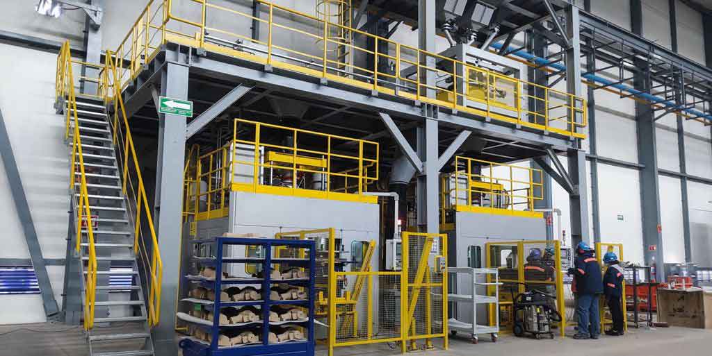
A resin sand casting process is employed. Key challenges and controls include:
1. Defect Prevention and Detection: Casting defects like shrinkage porosity, cold shuts, or gas holes must be minimized. Chemical analysis is performed on the molten metal before pouring. After initial rough machining, each casting undergoes thorough ultrasonic testing. Castings with defects exceeding the machining allowance are scrapped early. This staged inspection prevents valuable downstream processing time from being wasted on flawed steel castings.
2. Distortion Control: Differential cooling rates inevitably cause casting and heat treatment distortion, often manifesting as warping or twisting. This distortion directly translates into uneven thickness in the critical friction ring after machining, which can lead to non-uniform temperature distribution and stress. Controlling this is vital. Through process development, an optimal combination of heat treatment fixturing (to minimize warping during quenching and tempering) and a calibrated straightening process followed by stress relief was implemented. This successfully contained dimensional variation within the strict specifications.
3. Property Verification: For each heat-treat batch, mechanical test coupons (either attached to the castings or cut from a sacrificial disc) are evaluated. The results from several trial batches are shown below, all meeting the stringent targets. Metallographic examination confirmed a microstructure of tempered martensite/sorbite, which provides the optimal balance of strength and toughness for these steel castings.
| Batch No. | Tensile Strength (MPa) | Yield Strength (MPa) | Elongation (%) | Impact Energy (J) | Hardness (HBW) |
|---|---|---|---|---|---|
| Sample 1 | 1085 | 922 | 13.7 | 57 | 352 |
| Sample 2 | 1107 | 1021 | 13.1 | 50 | 368 |
| Sample 3 | 1088 | 998 | 13.4 | 58 | 347 |
| Sample 4 | 1127 | 1039 | 13.4 | 52 | 352 |
| Sample 5 | 1281 | 1202 | 11.4 | 40 | 375 |
1:1 Brake Dynamometer and Fatigue Testing
Qualified discs were assembled onto wheels and subjected to exhaustive testing on a UIC-certified 1:1 brake dynamometer according to the relevant technical standard. The test sequence included a series of braking applications under various speeds and pressures to measure performance parameters like maximum disc temperature, average friction coefficient, and wear.
The results were excellent. The highest recorded temperature of 570°C occurred during a drag brake test. Crucially, under the most severe condition of two consecutive emergency stops from maximum speed, the peak temperature was 405°C, aligning well with the earlier simulation prediction. The average friction coefficient remained stable between 0.30 and 0.45 across all tests. Following the dynamic performance test, the disc underwent a 1000-cycle fatigue endurance test. Post-test inspection revealed a smooth, crack-free friction surface with no signs of hot spots, and all fasteners remained secure and undamaged. The steel castings had passed all formal laboratory validation requirements.
Service Application and Conclusion
The developed cast steel brake discs have been successfully installed on prototype diesel locomotives. Since early 2019, these locomotives have undergone extensive route testing and service evaluation across diverse geographical and climatic regions in China, including the cold northeast, the arid northwest, and the mountainous southwest. Throughout this period, the braking system performance has been consistently satisfactory. Regular inspections of the discs show no evidence of cracking or other service-induced damage, confirming their reliability and durability in real-world operating conditions.
In conclusion, the successful development and application of this brake disc demonstrate:
1. The structural and thermal design, validated by finite element analysis and dynamometer testing, is fully capable of meeting the thermal loads imposed by 160 km/h railway service.
2. The selected low-alloy steel chemistry, combined with a controlled casting and heat treatment process, reliably produces steel castings with the required mechanical properties (strength >1050 MPa, hardness >290 HBW) and a favorable tempered microstructure. The implemented quality control measures effectively manage defects and distortion.
3. The product has passed all mandatory performance and fatigue tests per the industry standard and has proven its operational worth through prolonged service on high-speed diesel locomotives. This project confirms that advanced steel castings are a viable and high-performance solution for critical braking components in modern railway applications.