
In the field of advanced manufacturing, shell molding techniques have revolutionized the production of high-precision casting parts, offering superior dimensional accuracy and surface finish. This method significantly reduces metal cutting waste and machining time, while enabling mechanized and automated casting production. It is particularly advantageous for批量生产 of complex casting parts that demand tight tolerances and consistent quality. Our focus in this study is on the MT-2 buffer box, a critical casting part in railroad wagons that absorbs longitudinal impact energy, enhances train stability, and ensures safety. The quality of this casting part directly influences the overall performance of the buffer system, making process optimization essential. We conducted extensive experiments comparing three shell molding and core technologies: carbon dioxide hardening of water glass sand, Bonny resin silica sand, and Bonny resin pearl sand. Our goal is to identify the most efficient, environmentally friendly, and stable process for producing this casting part, with emphasis on multiple evaluations through tables and formulas.
Shell molding, also known as the Croning process, involves creating a thin, resin-bonded sand shell around a pattern to form molds and cores for casting parts. This technique offers remarkable benefits, including high dimensional precision (tolerances as tight as ±0.25 mm) and low surface roughness (Ra values below 6.3 μm) for the casting part. By reducing sand usage by 50-70% compared to traditional methods, it supports sustainable manufacturing. The following table summarizes key advantages of shell molding for casting parts:
| Aspect | Shell Molding | Traditional Sand Molding |
|---|---|---|
| Dimensional Accuracy | High (±0.25 mm) | Moderate (±0.5-1 mm) |
| Surface Roughness | Low (Ra < 6.3 μm) | Higher (Ra 12.5-25 μm) |
| Sand Usage per Casting Part | Reduced by 50-70% | High |
| Process Automation | Highly feasible | Limited |
| Suitable for Casting Parts | Complex, high-precision | Simple to moderate complexity |
The buffer box casting part is designed to withstand significant mechanical stresses, requiring meticulous工艺 design. Based on the characteristics of water glass sand and environmentally friendly Bonny resin sand, we established process parameters to ensure the integrity of the casting part. The overall shrinkage rate was set at 2%, with critical dimensions adjusted to 1.5% shrinkage. This is expressed mathematically for the casting part as:
$$ \text{Shrinkage Rate} = \frac{L_{\text{pattern}} – L_{\text{casting}}}{L_{\text{pattern}}} \times 100\% $$
where \( L_{\text{pattern}} \) is the pattern dimension and \( L_{\text{casting}} \) is the final dimension of the casting part. For a target casting part dimension \( L_{\text{casting}} \), the pattern dimension is calculated as:
$$ L_{\text{pattern}} = \frac{L_{\text{casting}}}{1 – 0.02} $$
Through iterative trials, we optimized局部尺寸 to stabilize the casting part dimensions, ensuring consistency across production batches.
The gating system for this casting part was designed as a closed-open type to facilitate slag removal and ensure平稳充型. The choke area \( A_c \) was determined based on fluid dynamics to control flow velocity \( v \) and volumetric flow rate \( Q \):
$$ A_c = \frac{Q}{v} $$
For the casting part, \( v \) was maintained below 2 m/s to avoid turbulence, with a liquid metal上升速度 of at least 40 mm/s. Insulated risers were employed to enhance feeding efficiency, increasing the process yield. The total浇注 weight for the casting part was 130 kg, with浇冒口 weight of 44 kg, resulting in a yield of 66.15%. The shell thickness for the casting part was set at 20 mm overall, with局部热节 areas reduced to 15 mm to promote sequential solidification and minimize defects in the casting part.
We performed solidification simulation using ProCAST software to validate the process for the casting part. The mesh division included the casting part, gating system, shell mold, and core. Simulation results indicated an internal defect level below grade 2 according to the Niyama criterion \( N \), defined as:
$$ N = \frac{G}{\sqrt{T}} $$
where \( G \) is the temperature gradient and \( T \) is the local solidification time. For the casting part, \( N \) values exceeded the critical threshold, confirming soundness. The temperature field showed all areas above the liquidus during filling, eliminating cold shut risks for the casting part. Velocity field analysis revealed充型 times of 18-20 seconds, affirming the design’s合理性 for the casting part.
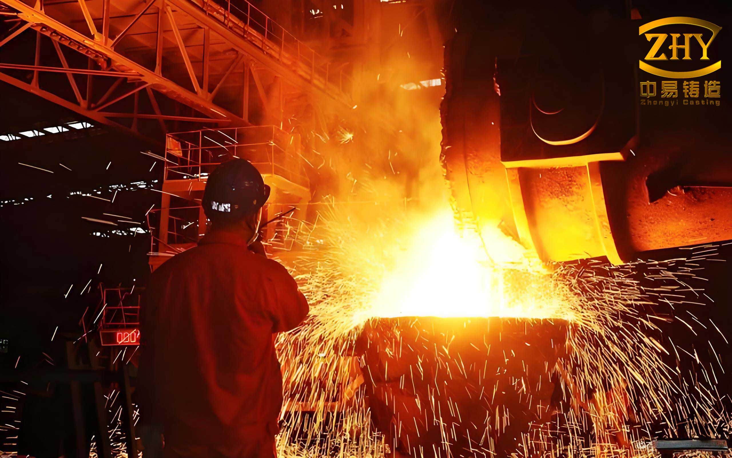
For production验证, we implemented three schemes using core shooting machines to produce shell molds and cores for the casting part. The detailed compositions and conditions are compared below:
| Scheme | Sand Type | Binder (wt.% of sand) | Additives | Curing Conditions | Shell Thickness (mm) |
|---|---|---|---|---|---|
| Scheme 1: Water Glass Sand | Natural selected silica sand | Water glass: 2.6% | Enhancer: 20% of water glass | CO₂ hardening at room temperature | 30 |
| Scheme 2: Bonny Resin Silica Sand | Natural selected silica sand | Bonny resin: 1.5% | Curing agent: 25% of resin, Enhancer: 0.6% of sand | 160°C for 210 s | 20 |
| Scheme 3: Bonny Resin Pearl Sand | Pearl sand (alumina-silicate) | Bonny resin: 1.5% (reduced to 1.1-1.3% in practice) | Curing agent: 25% of resin, Enhancer: 0.6% of sand | 160°C for 210 s | 20 |
In Scheme 1, the water glass sand shells for the casting part achieved an instantaneous tensile strength \( \sigma_t \) after CO₂ hardening, calculated as:
$$ \sigma_t = \frac{F}{A} \approx 0.9 – 1.10 \, \text{MPa} $$
where \( F \) is the force and \( A \) is the cross-sectional area. However, the final strength of 1.4-1.6 MPa proved inadequate for handling, leading to frequent cracking of shells during合型 and吊运 for the casting part. Moreover, core collapse occurred during pouring due to prolonged high temperatures, causing penetration defects in the casting part.
In Schemes 2 and 3, the Bonny resin sand shells were cured thermally, forming stable structures for the casting part. After合型, iron shot filling was employed to support the shells during pouring. The pouring temperature was set at 1580°C, with a pouring time of 15-20 seconds. After 4 hours, shakeout revealed the surface condition of the casting part. We observed that Scheme 3 produced casting parts with excellent surface quality, free from sand adhesion, whereas Scheme 2 casting parts showed局部粘砂, and Scheme 1 casting parts had severe adhesion.
Quality inspections were conducted comprehensively on the casting parts. For dimensional accuracy, we used a 3D scanner to compare actual contours with designed models. Key dimensions for the casting part were measured, with results summarized below:
| Scheme | Measurement Position | ϕ180 +0/-2 (mm) | 276 ±0.8 (mm) | ϕ199 ±1.6 (mm) | 143 +2/-1 (mm) | 320 ±1.6 (mm) | 227 +2.5/-1.5 (mm) | Dimensional Deviation for Casting Part |
|---|---|---|---|---|---|---|---|---|
| Scheme 2 | Upper | 179.2 | 275.8 | 198.5 | 142.5 | 319.2 | 226.5 | +1.25 mm max |
| Middle | 180.2 | 276.8 | 198.5 | 144.4 | 322.5 | 229.3 | ||
| Lower | 181.25 | 277.3 | 199.8 | 144.7 | 321.2 | 229.2 | ||
| Scheme 3 | Upper | 179.0 | 275.6 | 198.1 | 144.0 | 318.8 | 225.8 | +0.72 mm max |
| Middle | 179.8 | 276.3 | 198.8 | 144.4 | 322.3 | 228.0 | ||
| Lower | 180.72 | 277.0 | 199.28 | 144.7 | 321.4 | 278.4 |
All key dimensions for the casting part in Schemes 2 and 3 were within drawing tolerances, with Scheme 3 showing superior consistency. Statistical analysis for the casting part dimensions in Scheme 3 yielded mean \( \mu \) and standard deviation \( \sigma \). For example, for ϕ180:
$$ \mu = \frac{179.0 + 179.8 + 180.72}{3} = 179.84 \, \text{mm} $$
$$ \sigma = \sqrt{\frac{(179.0-179.84)^2 + (179.8-179.84)^2 + (180.72-179.84)^2}{3}} \approx 0.72 \, \text{mm} $$
This indicates a stable process for the casting part production.
Magnetic particle inspection on two casting parts per scheme revealed that Scheme 2 casting parts had severe cracks in inner cavities,多为毛细裂纹, while Scheme 3 casting parts were defect-free. Internal soundness was assessed through sectioning, showing dense structures without shrinkage cavities in all casting parts, meeting the stringent requirements for this casting part.
We analyzed each scheme’s impact on the casting part quality. For Scheme 1, water glass sand offered good退让性 and thermal conductivity, but the shell strength \( \sigma_t \) was insufficient for handling thin sections. The high-temperature behavior affected the casting part dimensions, with sand adhesion due to low耐火度. The heat transfer equation during solidification of the casting part is:
$$ \frac{\partial T}{\partial t} = \alpha \nabla^2 T $$
where \( T \) is temperature, \( t \) is time, and \( \alpha \) is thermal diffusivity. For water glass sand, \( \alpha \) is relatively high, but strength degradation compromised the casting part integrity.
In Scheme 2, Bonny resin silica sand led to crack formation in the casting part due to low thermal conductivity \( \kappa \) and high residual strength at elevated temperatures. The stress \( \sigma \) in the casting part during solidification can be modeled as:
$$ \sigma = E \cdot \epsilon $$
where \( E \) is Young’s modulus and \( \epsilon \) is strain. For silica sand shells, high \( E \) at high temperatures increased stress concentrations in热节 areas of the casting part, promoting cracks. Sand adhesion resulted from low耐火度 and溃散性, affecting the casting part surface.
Scheme 3, using Bonny resin pearl sand, demonstrated optimal performance for the casting part. Pearl sand has high耐火度 (over 1800°C) and excellent粒型, reducing resin demand by 20-25%. The lower resin content decreased high-temperature residual strength, enhancing溃散性 and preventing cracks in the casting part. The thermal conductivity \( \kappa \) of pearl sand is higher than silica sand, promoting uniform cooling of the casting part. The process capability index \( C_p \) for the casting part dimensions in Scheme 3 was calculated as:
$$ C_p = \frac{\text{Tolerance Width}}{6\sigma} $$
For dimension ϕ180, with a tolerance of 2 mm and \( \sigma \approx 0.72 \) mm, \( C_p \approx 0.46 \), indicating potential for further optimization, but still acceptable for the casting part.
Environmental and economic aspects were also considered. The Bonny resin pearl sand process reduces VOC emissions by 15-20% compared to silica sand for the casting part production. Pearl sand reuse rate exceeds 90%, minimizing waste. The table below compares environmental impacts per casting part:
| Parameter | Scheme 1: Water Glass Sand | Scheme 2: Bonny Resin Silica Sand | Scheme 3: Bonny Resin Pearl Sand |
|---|---|---|---|
| Resin Consumption (kg per casting part) | 0 (inorganic binder) | 1.5% of sand weight | 1.1-1.3% of sand weight |
| Sand Reusability (%) | Low (30-40%) | Moderate (60-70%) | High (90-95%) |
| VOC Emissions (relative) | Low | High | Medium |
| Energy Consumption for Curing | Low (CO₂ hardening) | High (thermal curing) | High (thermal curing) |
In conclusion, our research and practice on shell molding and core technology for railroad wagon buffer box casting parts reveal that Scheme 3 (Bonny resin pearl sand) is the optimal choice. It ensures high dimensional accuracy, excellent surface quality, and defect-free casting parts, with environmental benefits and efficiency. Scheme 1 is unsuitable due to handling issues and poor surface quality of the casting part, while Scheme 2 leads to cracks and sand adhesion in the casting part. We recommend adopting the Bonny resin pearl sand process for批量生产 of this critical casting part, with ongoing monitoring to enhance process capability. Future work could explore advanced simulation models for further optimization of the casting part production.