
The manufacturing of high-integrity, complex geometry components is a persistent challenge in the foundry industry, particularly for critical sand casting parts used in demanding applications. Among these, gray iron castings like upper rotary discs for heavy machinery must exhibit exceptional mechanical properties, dimensional stability, and soundness to withstand static and dynamic loads. The inherent complexities of such parts—characterized by significant variations in wall thickness, deep pockets, and internal cavities—often lead to defects during solidification, primarily shrinkage porosity and voids. These defects compromise the structural integrity and functional performance of the final component. This study presents a systematic approach to designing and optimizing the sand casting process for an HT300 gray iron upper rotary disc, leveraging advanced numerical simulation techniques to predict and subsequently eliminate solidification-related defects, thereby enhancing the quality and reliability of the produced sand casting parts.
The component under investigation is a large, plate-like structure functioning as a primary load-bearing and guiding element in machine tools. Its successful production as sand casting parts is paramount. The material specified is gray cast iron grade HT300, chosen for its excellent castability, good machinability, high compressive strength, and superior damping capacity. The nominal chemical composition is detailed in Table 1.
| Material Grade | C | Si | Mn | P | S |
|---|---|---|---|---|---|
| HT300 | 2.80-3.10 | 1.10-1.40 | 1.00-1.20 | <0.15 | ≤0.12 |
The three-dimensional geometry of the upper rotary disc, as analyzed in this study, reveals its challenging nature for sand casting. With overall dimensions of approximately 1281 mm × 1269.7 mm × 101 mm and a projected weight of over 500 kg, it features a large, relatively thin base plate intersected by numerous reinforcing ribs, bolt bosses, and a central hub. The wall thickness varies drastically, from a minimum of 15 mm in the web sections to a maximum of 113 mm at the boss and hub intersections, creating pronounced thermal masses or “hot spots.” These hot spots are prone to delayed solidification, leading to shrinkage defects if not properly fed. The casting’s functionality requires the machined surfaces, particularly the bottom face and bore surfaces, to be dense and free from defects to ensure proper bearing support and prevent oil seepage.
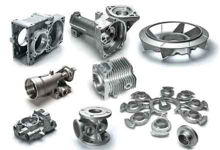
Given the component’s geometry and the requirement for sound sand casting parts, a robust casting process design is essential. The primary considerations include the orientation of the casting in the mold, the design of the gating system to ensure smooth filling, and the implementation of a feeding system (risers) to compensate for volumetric shrinkage during solidification. For this specific part, a horizontal pouring position was selected. Although an inverted position (pouring on the large flat face) could theoretically benefit the feeding of the thick sections now at the top, it introduces extreme complexity in mold-making, core setting, and finishing, making it impractical for typical sand casting production.
The design of the gating system is critical for achieving defect-free sand casting parts. Two fundamental schemes were evaluated: a bottom-gating system and a middle-gating system. Initial simulation trials indicated that while both led to defects in thick sections, the middle-gating system resulted in more extensive defect zones on the upper surface of the casting. Consequently, a pressurized, bottom-gating system was adopted for the initial design. This system promotes a calm, progressive fill from the bottom upwards, minimizing turbulence, mold erosion, and oxide formation. The initial gating system comprised one sprue, two runners, and seven ingates, with a choke area at the sprue base. The cross-sectional area ratio was designed to be 1.15 : 1.1 : 1. The filling time was calculated to be approximately 47 seconds for the initial design. Furan resin-bonded sand was selected for both the mold and cores due to its good dimensional accuracy, collapsibility, and suitability for producing complex sand casting parts.
The core of this optimization study lies in the application of numerical simulation. Using ProCAST, a dedicated finite element method (FEM) based casting simulation software, the entire process of mold filling, solidification, and defect formation was virtually replicated. Accurate simulation requires precise input of thermophysical properties and boundary conditions. The key parameters and material models used are summarized below:
- Casting Material: HT300 Gray Iron (database properties including temperature-dependent thermal conductivity, specific heat, density, and fraction solid).
- Mold/Core Material: Furan Resin Sand.
- Pouring Temperature: 1370°C.
- Interfacial Heat Transfer Coefficients (HTC):
- Metal/Sand: $$ h_{m-s} = 500 \text{ W/(m²·K)} $$
- Sand/Chill: $$ h_{s-c} = 500 \text{ W/(m²·K)} $$
- Metal/Chill: $$ h_{m-c} = 2000 \text{ W/(m²·K)} $$
- Mesh: A hybrid finite element mesh was generated, consisting of over 310,000 volume elements for the casting and gating system, ensuring sufficient resolution to capture thermal gradients in critical areas.
The heat transfer at the metal-mold interface is governed by Fourier’s law and Newton’s law of cooling. The energy equation solved during solidification can be expressed as:
$$
\rho c_p \frac{\partial T}{\partial t} = \nabla \cdot (k \nabla T) + \rho L \frac{\partial f_s}{\partial t}
$$
where $\rho$ is density, $c_p$ is specific heat, $T$ is temperature, $t$ is time, $k$ is thermal conductivity, $L$ is latent heat of fusion, and $f_s$ is the solid fraction. The accurate modeling of the latent heat release, linked to the fraction solid curve for gray iron, is crucial for predicting the correct solidification sequence and identifying isolated liquid pockets.
The simulation of the initial process design provided critical insights. The filling sequence was stable and complete, with no visible cold shuts or misruns. However, the solidification analysis revealed the fundamental flaw in the initial design: the absence of a dedicated feeding system. The Niyama criterion, a common indicator for predicting shrinkage porosity, along with the direct prediction of macroporosity, highlighted severe shrinkage defects concentrated in the major thermal centers. These included the central hub, the thick bosses surrounding the bolt circles, and the junctions between the ribs and the base plate. The defects manifested because these isolated hot spots solidified last, draining liquid metal from surrounding areas without any external source of molten metal to compensate for the volumetric shrinkage. This is a classic failure mode in poorly fed sand casting parts.
The quantitative analysis of the solidification sequence is vital. The local solidification time $\theta$ in a region is a key parameter. Regions with a high $\theta$ value are potential defect sites. The criterion for soundness often relates to the thermal gradient $G$ and the cooling rate $\dot{T}$ at the end of solidification. A modified Niyama criterion for gray iron can be considered for microporosity prediction. However, for the macroscopic shrinkage observed, the identification of the last point to solidify (the “hot spot”) is primary. The solidification modulus $M$, defined as the volume-to-cooling surface area ratio ($M = V/A$), is a useful heuristic for comparing the relative freezing times of different sections of a casting and for initial riser sizing. The thick sections of the upper rotary disc had significantly higher moduli than the thin walls, explaining the defect locations.
| Location | Approx. Modulus, M (cm) | Solidification Sequence |
|---|---|---|
| Thin Web Sections | ~0.8 | First |
| Central Hub | ~3.5 | Last (in casting) |
| Large Bosses | ~2.0 – 2.5 | Penultimate |
Based on the diagnostic simulation results, a comprehensive optimization strategy was implemented to transform the initial flawed design into a robust process capable of producing sound sand casting parts. The strategy had two pillars: 1) redesigning the gating system to improve thermal control, and 2) implementing an effective risering system to feed the isolated hot spots.
First, the gating system was switched from a bottom-gating to a top-gating scheme. While bottom-gating offers calm filling, for this particular geometry, it resulted in excessive temperature gradients from the bottom to the top by the end of filling. The thick sections at the top were relatively colder. The new top-gating design delivers hot metal directly onto the thick upper sections of the casting, creating a more favorable temperature distribution that supports directional solidification towards the risers placed on top. The optimized system used one sprue, one runner, and four ingates with an enlarged cross-sectional area to maintain a suitably short fill time.
Second, and most critically, a system of risers was designed and placed over the identified hot spots on the upper surface of the casting. The risers act as reservoirs of molten metal, compensating for the shrinkage in the casting body. For the major hot spots like the central hub and the large bosses, necked-down top risers were designed. For smaller thermal concentrations, conventional blind risers were used. The design followed established principles: the riser must solidify after the casting region it feeds, and it must contain sufficient volume to meet the shrinkage demand. The riser dimensions were calculated based on the modulus method. The required riser modulus $M_r$ must be greater than the casting modulus $M_c$ of the section it feeds. A typical factor is:
$$
M_r = 1.2 \times M_c
$$
Using this, the dimensions for cylindrical risers were determined. For example, for a feeding zone with $M_c \approx 3.0$ cm, the riser modulus $M_r$ should be >3.6 cm. For a cylindrical side riser with a height-to-diameter ratio of 1.5, the diameter $D_r$ can be derived from $M = V/A = (\pi D_r^2 H / 4) / (\pi D_r H + \pi D_r^2/4)$. Solving this gives the necessary riser size. The final riser configuration is summarized in Table 3.
| Riser Type | Quantity | Key Dimensions (mm) | Purpose |
|---|---|---|---|
| Necked Top Riser | 5 | Body Diameter: 180, Neck Diameter: 90, Height: 300 | Feed central hub and largest bosses |
| Blind Riser | 5 | Diameter: 80, Height: 180 | Feed smaller boss and rib junctions |
The simulation of the optimized process yielded dramatically improved results. The filling remained smooth and complete. More importantly, the solidification sequence was now controlled. The thin sections and lighter parts of the casting solidified first. The heavy sections began to solidify but were continuously fed by the liquid metal in the risers placed directly above them. Finally, the risers themselves solidified, becoming the last point of solidification in the entire system. This is the principle of directional solidification applied to complex sand casting parts.
The defect prediction plot for the optimized process confirmed the success of the strategy. The vast majority of the shrinkage porosity was successfully transferred from the critical functional areas of the casting body into the risers. The casting itself showed only a single, minor isolated defect in a non-critical area, a level of soundness fully acceptable for this application. Since all risers were placed on the upper surface—a non-functional area designated for machining—they can be easily removed during subsequent processing, leaving behind a sound sand casting part.
This case study underscores the immense value of numerical simulation in the modern foundry. For complex sand casting parts like the HT300 upper rotary disc, traditional trial-and-error methods are costly, time-consuming, and often unreliable. ProCAST simulation provided a virtual prototyping environment where different gating and feeding strategies could be evaluated rapidly and without material waste. The software’s ability to visualize temperature fields, track solidification fronts, and predict defect locations based on scientifically validated criteria was instrumental in diagnosing the problem and validating the solution.
The key to success was a two-fold optimization: repositioning the gate to create a more favorable thermal gradient and, decisively, implementing a correctly sized and positioned risering system based on modulus calculations and simulation feedback. The final optimized process design ensures the production of high-integrity sand casting parts that meet the stringent mechanical and quality requirements for heavy machinery components. This methodology—combining fundamental casting principles with powerful simulation tools—provides a robust framework for tackling the challenges associated with manufacturing other complex, heavy-section gray iron sand casting parts.