
The successful production of a large, high-integrity ductile iron casting is a symphony of precise engineering, metallurgical control, and rigorous process execution. This account details the comprehensive process design undertaken for a critical MA-type two-platen injection molding machine template, a component where structural soundness and dimensional stability of large plane surfaces are paramount. The challenges inherent in such a casting—significant variations in section thickness, the risk of shrinkage defects, and graphite degradation in heavy sections—demand a holistic approach from pattern design through to final inspection.
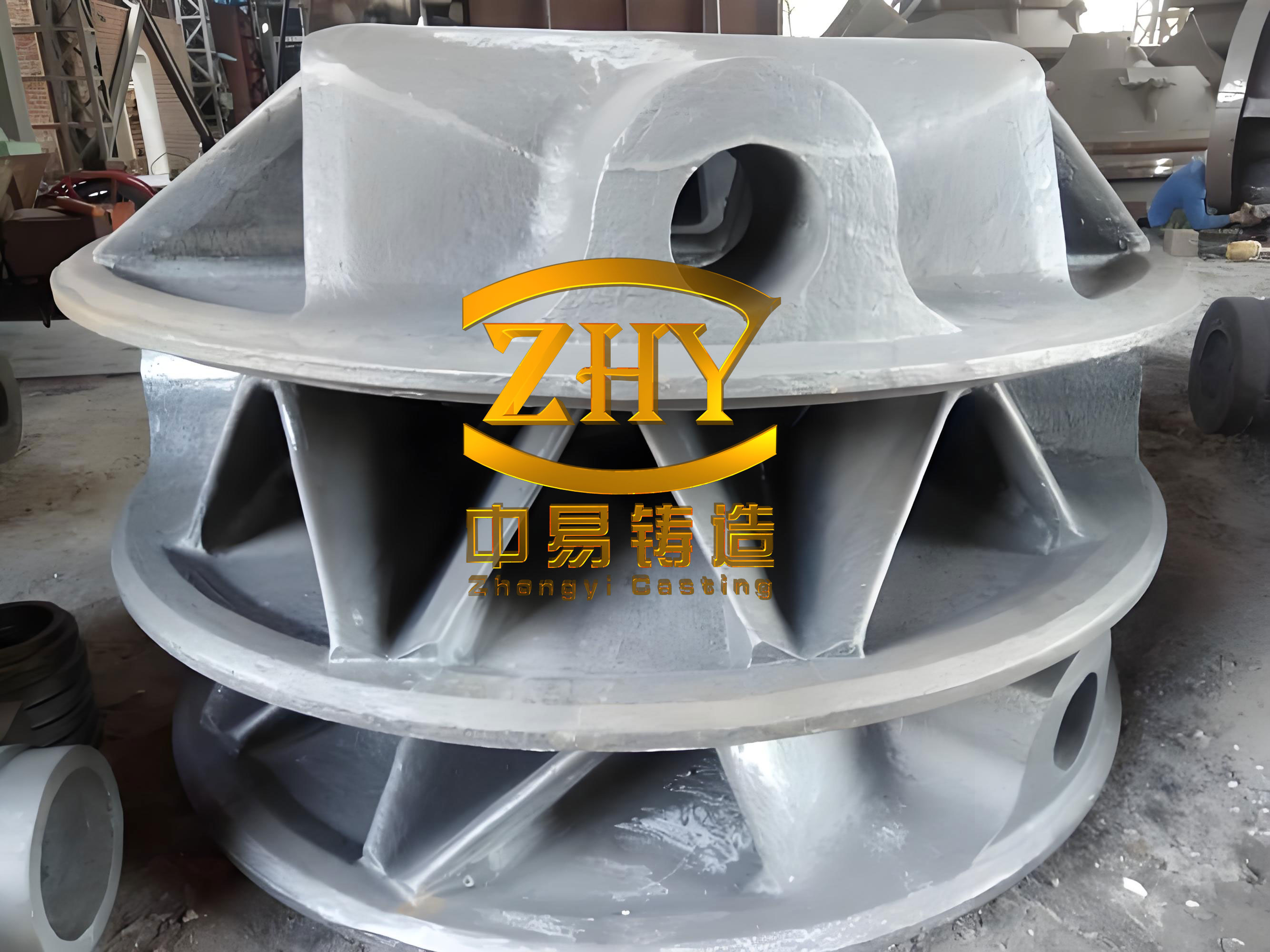
The casting in question, with a finished weight of 4.8 tonnes, presented a formidable geometry: overall dimensions of 1655 mm x 1616 mm x 430 mm, featuring a major machining plane for mold installation. The wall thickness varied dramatically from a minimum of 40 mm to a maximum of 160 mm. This non-uniformity is a classic recipe for differential cooling rates, leading to potential issues like shrinkage porosity, graphite flotation, or carbide formation in the thicker sections. The primary objective was to design a process that guaranteed internal soundness, a high nodule count, and consistent mechanical properties throughout the entire ductile iron casting, especially beneath its large, critical plane.
1. Foundry Method Design and Tooling Strategy
Given the component’s structure, a two-part flask molding process was selected with the major plane facing upward. The parting line was established at this plane’s perimeter. To ensure dimensional accuracy and pattern stability—critical for large flat surfaces—the wooden pattern was constructed on a robust welded steel frame and securely fastened to the molding board. Machining allowances were strategically applied: 15 mm on the cope side (top), 8 mm on the drag side and lateral faces.
The gating system is the circulatory system of the casting process. For this large ductile iron casting, the principles of “high flow rate, low velocity, and smooth, clean filling” were paramount. A semi-open, bottom-gating system was engineered. This design promotes a calm, controlled rise of metal in the mold cavity, minimizing turbulence, slag entrainment, and surface defects. The ingates were positioned along the longer sides of the casting to ensure even metal distribution. Ceramic tubes were utilized for the sprue and ingates to prevent mold erosion. The system’s choke was placed at the sprue base, with the following area ratios:
$$\Sigma F_{sprue} : \Sigma F_{runner} : \Sigma F_{ingate} = 1 : 1.11 : 1.07$$
Specific cross-sectional areas were: Sprue = 81 cm², Runner = 90 cm², Ingates = 86.4 cm².
To address the localized cooling requirements of the thick sections and the large plane, an array of external chills was strategically placed on the mold cavity surface corresponding to these regions. This practice accelerates solidification at these points, promoting directional solidification towards the feeding heads and ensuring soundness. The mold and core sand properties were carefully controlled; excessive strength was avoided to prevent undue restraint on the contracting ductile iron casting.
2. Metallurgical Process Design and Control
The foundation of a high-quality ductile iron casting lies in its chemical composition and melt treatment. The target chemistry was designed to achieve QT450-10 grade properties in the heavy-sectioned casting.
| Element | Target Range (wt.%) | Rationale |
|---|---|---|
| C | 3.45 – 3.65 | High carbon equivalent for graphitization, improves castability and reduces shrinkage tendency. |
| Si | 2.3 – 2.5 | Strong graphitiser, final level controlled via inoculation. |
| Mn | < 0.60 | Minimized to reduce segregation and the risk of intercellular carbides. |
| P | < 0.02 | Minimized to avoid phosphide eutectic, which embrittles the matrix. |
| S | < 0.015 | Very low level is crucial for efficient Mg treatment and high nodule count. |
| Mgres | 0.03 – 0.05 | Residual magnesium for secure nodularization. |
| REres | 0.01 – 0.03 | Residual rare earths to counteract deleterious trace elements. |
The treatment process was multi-stage. A Fe-Si-Mg-RE alloy was used for nodularization via the sandwich method in a preheated ladle at 1460-1480°C. The reaction was vigorous and controlled. Immediately after, a robust inoculation practice was implemented to ensure a high nodule count and fine graphite structure, which is vital for the mechanical properties of the ductile iron casting. This involved:
- Pre-inoculation: 0.3% of foundry-grade Fe-Si alloy placed over the nodularizing alloy.
- Post-inoculation: 0.2% of a proprietary inoculating block added after slag removal.
- Stream Inoculation: 0.15% of fine-grain inoculant added during tapping into the pouring ladle.
The effectiveness of inoculation in preventing undercooled graphite (e.g., chunky or exploded forms) in heavy sections can be related to the growth kinetics of graphite nodules. The increase in nodule count (N) drastically reduces the diffusion distance for carbon atoms, favoring stable growth. The relationship can be conceptually framed as the inter-nodular spacing (λ) being inversely proportional to the cube root of the nodule count:
$$\lambda \propto \frac{1}{\sqrt[3]{N}}$$
A higher N from effective inoculation leads to a smaller λ, ensuring a finer, more uniform matrix and better properties.
3. Solidification Control and Feeding Principles
For a ductile iron casting, solidification is unique due to the expansion associated with graphite precipitation during the eutectic reaction. This expansion can be harnessed to counteract the shrinkage of the austenitic matrix, a principle known as “autofeeding” or “feeding with internal pressure.” The key is to control the rate of this expansion relative to the casting’s rigidity. The modulus (Volume/Surface Area ratio) of different sections dictates their cooling rate and feeding requirements.
The thermal gradient and solidification sequence were managed through the combined use of chills (increasing local cooling rate) and risers. The goal was to establish directional solidification paths from the thick, hot sections towards the risers. The chills on the large plane effectively increased the effective surface area of that region, reducing its thermal modulus and bringing its solidification time closer to that of thinner walls, thereby reducing the window for shrinkage formation. The equilibrium for sound solidification in ductile iron casting can be expressed by considering the volumetric balance:
$$V_{liq\rightarrow austenite} + V_{graphite expansion} – V_{macroshrinkage} = \Delta V_{net}$$
Where a positive or near-zero ΔVnet indicates soundness. The process design aimed to maximize the contribution of Vgraphite expansion through good inoculation and to minimize Vmacroshrinkage through controlled cooling.
4. Quality Verification and Results
The efficacy of the entire process design was validated through rigorous testing of cast-on samples (representative of the casting’s thick section) and non-destructive testing (NDT) of every production casting.
The metallographic and mechanical test results from the cast-on blocks confirmed that the ductile iron casting met and exceeded the QT450-10 specification.
| Property | Standard Requirement | Actual Result |
|---|---|---|
| Nodularity | ≥ 90% | 95% |
| Graphite Size (ASTM) | 4 – 7 | 6 |
| Tensile Strength (MPa) | ≥ 390 | 410 |
| Yield Strength (MPa) | ≥ 260 | 285 |
| Elongation (%) | ≥ 10 | 13.5 |
| Hardness (HB) | 160 – 210 | 165 |
Furthermore, 100% of the castings were subjected to ultrasonic testing according to EN 12680-3 to detect internal discontinuities and magnetic particle inspection per EN 1369 to reveal surface flaws. The consistent passage of these NDT protocols confirmed the internal and external soundness of the large-plane ductile iron casting, fulfilling all acceptance criteria.
5. Conclusion and Process Synthesis
The successful serial production of this demanding ductile iron casting underscores the importance of an integrated process design. Key takeaways include:
- Tooling Rigidity: A stable, robust pattern is non-negotiable for maintaining the dimensional accuracy of large flat surfaces.
- Hydraulic Design: A semi-open, bottom-gating system with ceramic components provides the calm filling necessary for clean, defect-free castings.
- Thermal Management: Strategic use of chills is essential to modulate solidification times in variable sections, working in concert with the intrinsic graphite expansion of ductile iron casting to achieve soundness.
- Metallurgical Precision: Tight control of base chemistry (low Mn, P, S), coupled with a controlled nodularization and a powerful, multi-stage inoculation practice, is critical to achieving high nodularity, fine graphite, and consistent mechanical properties in heavy sections.
- Process Control: Strict adherence to defined parameters for pouring temperature (~1340°C), pouring time, and sand properties closes the loop on a repeatable, high-quality manufacturing process.
This case study demonstrates that by systematically addressing模具 design, fluid dynamics, solidification science, and metallurgy, the inherent challenges of producing large, complex ductile iron castings with stringent quality requirements can be reliably overcome. The process stands as a validated blueprint for similar heavy-section, high-integrity ferrous components.