
In modern manufacturing, the quest for materials that combine excellent mechanical properties with cost-effectiveness is perpetual. Among various engineering materials, ductile iron casting has emerged as a prominent choice for critical, high-load components. The unique graphite nodular morphology within a ferritic or pearlitic matrix grants this material a remarkable combination of castability, good machinability, and respectable strength and ductility, all at a relatively low production cost. These attributes have solidified its position as the material of choice for manufacturing large-scale, geometrically complex parts subjected to demanding service conditions.
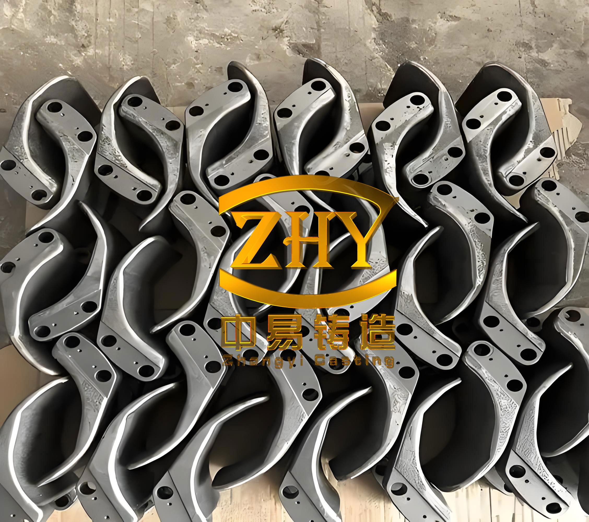
Typical applications include camshafts, crankshafts, heavy-duty gearboxes, valve bodies, and large pump housings. However, the operational environments for these components are increasingly severe, often involving elevated temperatures, high contact pressures, significant impact loads, abrasive or adhesive wear, and exposure to corrosive media. While the bulk properties of ductile iron casting are often sufficient for structural integrity, the surface—the first line of defense against these degradation mechanisms—can become the limiting factor. Surface-initiated failures like excessive wear, pitting, and corrosion can lead to premature component retirement, causing unplanned downtime and significant economic loss. Therefore, enhancing the surface-specific properties of ductile iron components—namely hardness, wear resistance, and corrosion resistance—without compromising the advantageous bulk properties of the substrate is a critical engineering challenge.
Traditional surface hardening techniques for ductile iron casting, such as induction hardening, flame hardening, or nitriding, have been employed with varying degrees of success. While they improve surface hardness, their limitations are notable. These processes often have limited control over case depth, can induce undesirable distortions due to large heat-affected zones, and may not significantly improve corrosion resistance. Furthermore, some techniques are not well-suited for selective area treatment or for adding material to repair worn surfaces. This gap in surface engineering capabilities has driven the adoption of advanced additive and hybrid manufacturing processes.
Laser cladding has risen as a transformative surface engineering technology. It is fundamentally a directed energy deposition process where a focused laser beam creates a melt pool on a substrate material, into which metallic powder or wire is synchronously fed. The feedstock material melts and rapidly solidifies, forming a dense, metallurgically bonded coating or clad layer. This technique offers unparalleled advantages: minimal dilution of the coating by the substrate, a small and controllable heat-affected zone (HAZ) that preserves the base metal’s properties, high process flexibility for complex geometries and localized treatment, and the ability to deposit a wide range of advanced alloys not achievable through casting. In recent years, a high-productivity variant known as High-Speed Laser Cladding (HSLC) has gained prominence. By utilizing specialized nozzle designs and optimized process dynamics, HSLC achieves cladding speeds an order of magnitude higher than conventional laser cladding (often in the range of 50-200 m/min versus 0.5-2 m/min). This results in exceptional efficiency, even lower dilution rates (typically <5%), and a remarkably smooth surface finish that often requires minimal post-process machining. The extremely high cooling rates associated with HSLC also lead to refined microstructures, which can further enhance coating performance.
The selection of cladding material is paramount. For surface modification of ferrous substrates like ductile iron casting, Fe-based, Co-based, and Ni-based alloys are the primary candidates. Nickel-based alloys are particularly attractive for several reasons. They generally offer an excellent balance of high temperature strength, good toughness, and outstanding corrosion and oxidation resistance. A critical consideration when cladding onto cast iron substrates is the high carbon content (typically 3.0-4.0 wt%). During laser processing, carbon from the substrate can diffuse into the molten clad pool. In many alloy systems, this can lead to the formation of hard, brittle carbides and even martensitic structures at the interface or within the clad, potentially causing cracking or poor bonding. However, nickel has a very low solubility for carbon. By employing a Ni-based alloy with a high nickel content as the cladding material, it acts as a effective barrier, significantly inhibiting carbon diffusion from the ductile iron substrate. This “carbon-blocking” effect helps prevent the formation of brittle phases at the critical interface region, promoting a sound, crack-free metallurgical bond. The high nickel content also provides inherent compatibility and reduces the risk of galvanic corrosion between the coating and the iron-based substrate.
While previous studies have explored laser cladding on ductile iron, research focusing specifically on the high-speed variant and providing a comprehensive analysis of the resulting coating’s tribological and electrochemical properties remains less common. This work aims to address this gap. The objective is to systematically investigate the surface modification of ductile iron casting using High-Speed Laser Cladding to deposit a high-nickel-content alloy coating. The study will encompass a detailed analysis of the coating’s formation, microstructure, phase composition, and its resultant surface performance in terms of hardness, wear resistance, and corrosion resistance, thereby establishing a foundational understanding for industrial application.
Materials and Experimental Methodology
The substrate material employed in this investigation was a standard grade of ductile iron (nodular cast iron). The chemical composition of the substrate, as determined by optical emission spectroscopy, is provided in Table 1. The microstructure consisted of graphite nodules embedded in a predominantly ferritic matrix, which is typical for good ductility and machinability.
| Element | Ductile Iron Substrate | Ni-Based Alloy Powder |
|---|---|---|
| C | 3.72 | 0.08 |
| Si | 2.67 | 2.42 |
| Mn | 0.20 | – |
| P | 0.05 | – |
| S | 0.02 | – |
| Cr | 0.12 | 1.42 |
| Ni | 0.47 | Bal. |
| B | – | 1.36 |
| Fe | Bal. | 0.41 |
The cladding feedstock was a gas-atomized, spherical Ni-based alloy powder with a high nominal nickel content exceeding 95 wt.%. The powder particle size distribution was tightly controlled, with a median diameter (D50) of approximately 38 µm. This size range ensures good flowability for consistent powder feeding and efficient melting kinetics under the high-speed laser beam. The detailed composition is also listed in Table 1. Key alloying additions include chromium for solid solution strengthening and corrosion resistance, boron and silicon for lowering the melting point and improving wetting characteristics, and carbon in a controlled amount to facilitate the formation of hardening carbide phases.
The high-speed laser cladding system integrated a high-power fiber laser (RFL-C4000) with a maximum output of 4 kW, coupled to a multi-axis KUKA robotic arm for precise movement control. A coaxial cladding nozzle, optimized for high-speed deposition, was used to deliver the powder concentrically into the laser focus point. The entire process was conducted within an enclosure purged with argon to prevent oxidation. After extensive preliminary trials to establish a stable melt pool and a defect-free bead geometry, the following optimal parameters were selected for single-track and subsequent multi-layer overlapping cladding:
| Parameter | Value | Unit |
|---|---|---|
| Laser Power (P) | 2000 | W |
| Scanning Speed (V) | 30 | mm/s (0.03 m/s) |
| Powder Feed Rate (ṁ) | 2.5 | rev/min (Calibrated to ~10 g/min) |
| Beam Diameter (d) | ~2.0 | mm |
| Overlap Ratio | 66.7 | % |
| Shielding/Powder Carrier Gas | Argon | – |
The energy density per unit length, a critical parameter, can be expressed as:
$$ E_l = \frac{P}{V} $$
For our parameters, $$ E_l = \frac{2000 \text{ W}}{0.03 \text{ m/s}} \approx 66.7 \text{ kJ/m} $$
This moderate linear energy density, combined with high speed, is characteristic of HSLC, promoting low dilution and high cooling rates.
Post-cladding, samples were sectioned perpendicular to the cladding direction using electrical discharge machining (EDM). The cross-sections were then mounted, ground with successively finer silicon carbide papers, and polished to a mirror finish using diamond suspensions for microstructural analysis. Microstructural characterization was performed using a field emission scanning electron microscope (FE-SEM, JSF-7001) equipped with an energy dispersive X-ray spectroscopy (EDS) system. Phase identification was conducted via X-ray diffraction (XRD, Empyrean) using Cu-Kα radiation, scanning from 20° to 90° (2θ) with a step size of 0.02°.
The macro- and micro-hardness were evaluated. Macro-hardness (Rockwell B scale, HRB) was measured on the polished top surface of the coating. Micro-hardness profiles were obtained on the polished cross-section from the coating top surface, through the interface, and into the substrate using a Vickers micro-hardness tester with a 200 gf load and a 15 s dwell time (HV0.2).
Dry sliding wear tests were conducted using a ball-on-disk tribometer under ambient conditions. The counterpart was a 6 mm diameter Si3N4 ceramic ball. The test parameters were: normal load of 30 N, sliding speed of 5 m/min, total sliding distance of 300 m (60 min duration), and a wear track radius of 5 mm. The wear volume loss was calculated by measuring the cross-sectional area of the wear track using a 3D optical profilometer and multiplying by the track circumference. The specific wear rate, Ws, was calculated as:
$$ W_s = \frac{V}{F_N \cdot S} $$
where V is the wear volume loss (mm³), FN is the normal load (N), and S is the total sliding distance (m). The units are mm³/(N·m). Wear scar morphologies were examined using SEM to identify the dominant wear mechanisms.
Electrochemical corrosion behavior was assessed using a standard three-electrode cell in a 3.5 wt.% NaCl aqueous solution at room temperature (simulating a marine atmosphere). The working electrode was the tested sample with an exposed area of 1 cm², a saturated calomel electrode (SCE) served as the reference, and a platinum mesh was the counter electrode. Open circuit potential (OCP) was monitored for 1800 seconds to achieve stability. Potentiodynamic polarization tests were then conducted from -0.25 V vs. OCP to +1.2 V vs. SCE at a scan rate of 0.5 mV/s. Electrochemical impedance spectroscopy (EIS) measurements were performed at the OCP with a sinusoidal potential perturbation of 10 mV amplitude over a frequency range from 100 kHz to 10 mHz. The corrosion morphology after polarization was observed using SEM.
Results and Discussion
Coating Macrostructure, Interface, and Phase Composition
The high-speed laser cladding process successfully fabricated a continuous, dense, and uniform Ni-based alloy coating on the ductile iron substrate. The single-layer coating thickness was measured to be approximately 0.86 mm. At low magnification, the coating exhibited a fine, overlapping bead structure with a wavy interface, characteristic of the rapid solidification and overlapping thermal cycles. Crucially, no macroscopic defects such as cracks, pores, or lack-of-fusion were observed, indicating a stable and well-controlled cladding process suitable for the ductile iron casting substrate.
Higher magnification SEM analysis of the coating-substrate interface revealed critical details. The interface line was distinct but irregular, demonstrating a metallurgical bond. Notably, the graphite nodules from the substrate were observed to be partially dissolved at the interface, with a thin, diffusion-affected zone in the substrate adjacent to the melt boundary. However, the extent of this interaction was remarkably limited compared to conventional laser cladding processes. This is a direct consequence of the high nickel content in the clad material and the low dilution inherent to HSLC. Nickel’s low carbon solubility effectively impedes the massive influx of carbon from the ductile iron into the molten pool. The dilution rate, estimated from cross-sectional area measurements, was calculated to be less than 5%. The dilution percentage D can be expressed as:
$$ D (\%) = \frac{A_s}{A_c + A_s} \times 100 $$
where As is the cross-sectional area of the substrate melted and mixed into the clad, and Ac is the area contributed by the clad powder. The low value of D confirms minimal substrate melting, which is key to preventing carbon pickup and the associated brittleness. This “carbon-blocking” effect is fundamental to achieving a sound coating on high-carbon substrates like ductile iron casting.
The XRD patterns for the ductile iron substrate and the Ni-based coating are distinctly different. The substrate pattern shows sharp peaks corresponding to α-Fe (ferrite) and a broad peak for graphite. In contrast, the coating’s XRD spectrum is more complex. The primary phase is identified as a nickel-based solid solution, γ-Ni, with a face-centered cubic (FCC) structure. The lattice parameter of this γ-Ni phase is slightly expanded compared to pure nickel, indicating significant solid solution strengthening from alloying elements like Cr and Si. The other distinct peaks are indexed to hard, intermetallic and carbide phases: chromium carbide (Cr23C6), nickel silicide (Ni2Si), and nickel boride (Ni3B). The formation of these phases is expected given the composition of the powder (Cr, Si, B, C). During the extreme non-equilibrium solidification of HSLC, these elements are rejected from the primary γ-Ni dendrites and segregate to interdendritic regions, where they combine to form these hard, second-phase particles. The presence of this multi-phase microstructure, comprising a tough γ-Ni matrix reinforced by hard particles, is the microstructural foundation for the enhanced mechanical and chemical properties of the coating.
Hardness Profile and Enhancement
The surface hardness of the coated ductile iron was significantly improved. The average Rockwell B hardness (HRB) of the as-clad top surface was 300.5 HRB. In comparison, the uncoated ductile iron substrate had an average hardness of 190.1 HRB. This represents a substantial increase in surface hardness. The hardness enhancement ratio RH can be quantified as:
$$ R_H = \frac{H_{coating}}{H_{substrate}} = \frac{300.5}{190.1} \approx 1.58 $$
Therefore, the Ni-based coating provides a surface that is approximately 1.58 times harder than the original ductile iron casting. This 58% improvement is attributed to the synergistic effects of multiple strengthening mechanisms operating within the coating’s microstructure.
- Solid Solution Strengthening: The γ-Ni matrix is supersaturated with alloying elements like Cr and Si, causing lattice strain that impedes dislocation motion.
- Precipitation (or Second-Phase) Strengthening: The fine, uniformly distributed hard phases (Cr23C6, Ni2Si, Ni3B) act as effective barriers to dislocation glide and grain boundary sliding.
- Grain Refinement Strengthening (Hall-Petch Effect): The ultra-high cooling rates (estimated to be in the range of 105-106 K/s) of HSLC result in a very fine cellular-dendritic microstructure. The relationship is given by:
$$ \sigma_y = \sigma_0 + k_y \cdot d^{-1/2} $$
where σy is the yield strength, σ0 is the lattice friction stress, ky is the strengthening coefficient, and d is the average grain size. The refined grains contribute directly to higher strength and hardness.
The cross-sectional micro-hardness profile further illustrates the performance gradient. The hardness is highest at the coating surface (around 320-350 HV0.2), remains consistently high through the bulk of the coating (~300 HV0.2), shows a sharp transition across the narrow interface, and drops to the substrate level of ~180 HV0.2. The absence of a pronounced, softened heat-affected zone in the substrate is another benefit of the low heat input HSLC process, preserving the base properties of the ductile iron casting.
| Property | Ductile Iron Substrate | Ni-Based Coating | Improvement |
|---|---|---|---|
| Average Surface Hardness | 190.1 HRB | 300.5 HRB | +58% (Ratio: 1.58x) |
| Average Wear Mass Loss | 5.10 mg | 1.75 mg | -65.7% |
| Calculated Specific Wear Rate | ~8.5 x 10⁻⁴ mm³/(N·m) | ~2.9 x 10⁻⁴ mm³/(N·m) | -66% |
| Maximum Wear Track Depth | 171.2 µm | 87.63 µm | -49% |
Wear Resistance and Mechanisms
The tribological performance of the coated surface was markedly superior. Under identical sliding wear conditions against a Si3N4 counterface, the Ni-based coating exhibited an average mass loss of 1.75 mg, while the uncoated ductile iron suffered a loss of 5.10 mg (Table 3). This corresponds to a 65.7% reduction in wear. The specific wear rate, a more fundamental property, decreased by approximately 66%. The wear track depth profiles provided complementary evidence: the maximum depth for the coating was 87.63 µm, less than half of the 171.2 µm measured for the substrate.
SEM analysis of the wear scars revealed fundamentally different wear mechanisms, explaining the performance disparity. The wear surface of the ductile iron substrate showed deep, continuous grooves (ploughing) and evidence of adhesive material transfer and subsequent delamination. This is classic adhesive and abrasive wear, typical for a relatively soft metallic surface sliding against a hard ceramic. The ferritic matrix is easily penetrated and ploughed by the hard counterface asperities or by fractured carbide debris (third-body abrasion).
In stark contrast, the wear scar on the Ni-based coating was significantly shallower and smoother. The dominant features were fine, shallow scratches or micro-ploughing marks, indicative of mild abrasive wear. The hard second-phase particles (carbides, borides, silicides) effectively protect the γ-Ni matrix from deep penetration. Some small, localized spalling pits were observed, likely due to the fatigue-induced fracture and pull-out of these hard particles under cyclic loading. However, the overall material removal rate was low. The coating’s wear resistance can be modeled considering its composite nature. The relative wear resistance WR is often related to hardness H and fracture toughness Kc. For abrasive wear dominated by micro-ploughing, Archard’s law provides a simplified view:
$$ V = k \cdot \frac{F_N \cdot S}{H} $$
where V is wear volume and k is a wear coefficient. The inverse relationship with hardness is evident. The coating’s high composite hardness (from matrix strength and hard phases) directly reduces k and thus the wear volume V, validating the experimental data for the modified ductile iron casting surface.
Electrochemical Corrosion Behavior
The electrochemical tests in 3.5% NaCl solution demonstrated a clear improvement in the corrosion resistance of the ductile iron surface after cladding. The potentiodynamic polarization curves for both materials are presented schematically. Key corrosion parameters extracted via Tafel extrapolation are summarized in Table 4.
| Parameter | Ductile Iron Substrate | Ni-Based Coating |
|---|---|---|
| Corrosion Potential, Ecorr (vs. SCE) | -723.6 mV | -536.5 mV |
| Corrosion Current Density, icorr | 4.467 µA/cm² | 3.156 µA/cm² |
| Polarization Resistance, Rp (Estimated) | Lower | Higher |
The Ni-based coating exhibited a noble shift in corrosion potential (Ecorr) of +187.1 mV compared to the substrate. A more positive Ecorr generally indicates a lower thermodynamic tendency for corrosion. More importantly, the corrosion current density (icorr), which is proportional to the corrosion rate, was reduced by approximately 30% for the coating. This quantitative measure confirms a lower kinetic rate of anodic dissolution.
The EIS data provided further robust evidence. The Bode magnitude plots showed that the impedance modulus |Z| at low frequency (0.01 Hz), which is representative of the charge transfer resistance (Rct) and thus inversely related to corrosion rate, was significantly higher for the coating. The low-frequency impedance for the coating was approximately 4300 Ω·cm², roughly 5.7 times greater than the ~750 Ω·cm² measured for the substrate. The phase angle plots also suggested a more capacitive behavior for the coated surface over a broader frequency range, indicative of a more protective and stable surface film.
Post-corrosion surface morphology observations aligned with the electrochemical data. The uncoated ductile iron showed severe localized attack. The graphite nodules, being cathodic relative to the ferritic matrix, promoted galvanic corrosion. The surrounding iron was preferentially dissolved, leaving deep pits and eroded nodules, with a maximum pit depth exceeding 50 µm. The coating surface, however, showed only generalized, shallow attack with a fine, granular appearance. The maximum corrosion depth was around 13-14 µm, less than a third of that on the substrate. The uniform corrosion suggests the formation of a more stable, protective passive film, likely enriched in chromium oxides/hydroxides from the coating’s composition. The high nickel content itself provides inherent nobility and stability in chloride environments. This shift from severe localized pitting (substrate) to mild uniform corrosion (coating) represents a critical improvement for the long-term durability of ductile iron casting components in corrosive service.
Conclusions and Industrial Implications
This comprehensive investigation demonstrates that High-Speed Laser Cladding (HSLC) is a highly effective and efficient technology for the surface modification of ductile iron castings. By employing a high-nickel-content alloy powder, a dense, metallurgically sound coating was successfully fabricated. The key findings are synthesized as follows:
- Process and Microstructure: HSLC parameters (P=2 kW, V=30 mm/s) produced a ~0.86 mm thick coating with minimal dilution (<5%). The high Ni content effectively suppressed carbon diffusion from the substrate, preventing brittle phase formation at the interface. The coating exhibited a multi-phase microstructure consisting of a γ-Ni solid solution matrix reinforced with hard Cr23C6, Ni2Si, and Ni3B phases.
- Mechanical Performance: The surface hardness of the ductile iron was increased by 58%, with an average hardness ratio of 1.58 (Coating/Substrate). This enhancement is attributed to solid solution strengthening, dispersion strengthening from hard phases, and grain refinement due to rapid solidification.
- Wear Performance: The wear resistance was drastically improved. The coated sample showed a 65.7% reduction in wear mass loss and a ~66% lower specific wear rate compared to the uncoated substrate. The wear mechanism shifted from severe adhesive-abrasive wear (in the substrate) to mild abrasive wear with minor spalling (in the coating).
- Corrosion Performance: In a 3.5% NaCl solution, the Ni-based coating demonstrated superior electrochemical corrosion resistance. The corrosion potential (Ecorr) shifted positively by 187.1 mV, and the corrosion current density (icorr) decreased by ~30%. Low-frequency impedance increased by a factor of ~5.7. The failure mode changed from deep galvanic pitting around graphite nodules (substrate) to shallow, uniform surface attack (coating).
The implications for industries utilizing ductile iron casting are substantial. Components such as pumps for saline water, valves in chemical processing, marine engine parts, and wear-prone industrial machinery can have their service life extended significantly. HSLC offers a pathway not only for manufacturing new components with enhanced surfaces but also for repairing and refurbishing worn or corroded ductile iron parts, restoring them to a condition superior to their original state. The process’s speed, precision, and low heat input make it economically viable for both batch production and individual repair operations. Future work may explore the optimization of coating composition (e.g., adding Mo for pitting resistance or WC particles for extreme abrasion resistance), multi-layer cladding for thicker deposits, and the performance under combined wear-corrosion (tribocorrosion) conditions, further unlocking the potential of this surface engineering strategy for ductile iron components.