
The landscape of manufacturing is undergoing a profound transformation, driven by the convergence of new technologies with established industrial processes. Among these, 3D printing, or Additive Manufacturing (AM), has transitioned from a prototyping novelty to a production-ready technology capable of disrupting traditional workflows. In the foundry industry, the integration of Binder Jetting 3D printing for sand molds and cores—often referred to as 3D Sand Printing (3DSP)—with conventional pattern-making and molding techniques is creating a new paradigm: hybrid or rapid casting. This approach is particularly impactful for the production of large, complex, and low-volume castings where the high cost and long lead times associated with traditional tooling are prohibitive. This article details a first-person account of applying a “3D Printing + Traditional Mold” strategy for the rapid development and successful first-time production of a supercritical steam turbine’s medium-pressure outer cylinder—a massive and critical ductile iron casting.
The traditional production of major power generation components like turbine casings involves significant challenges. These ductile iron castings are characterized by their enormous size, intricate internal geometries, stringent quality requirements, and typically low batch volumes. The investment in full-scale wooden or metal patterns and core boxes for a single casting or a small batch is economically difficult to justify. Furthermore, any design iteration necessitates costly and time-consuming modifications to the physical tooling, stifling innovation and rapid response to customer needs. The advent of 3DSP offers a solution by enabling the direct digital fabrication of complex sand cores and molds without any pattern equipment. However, for very large castings, completely printing the entire mold can be constrained by printer build volume and can become expensive. The hybrid approach, which strategically combines 3D printed elements with existing conventional tooling, emerges as an optimal balance between speed, cost, and practicality for legacy product variants or new designs with partial similarities to existing ones.
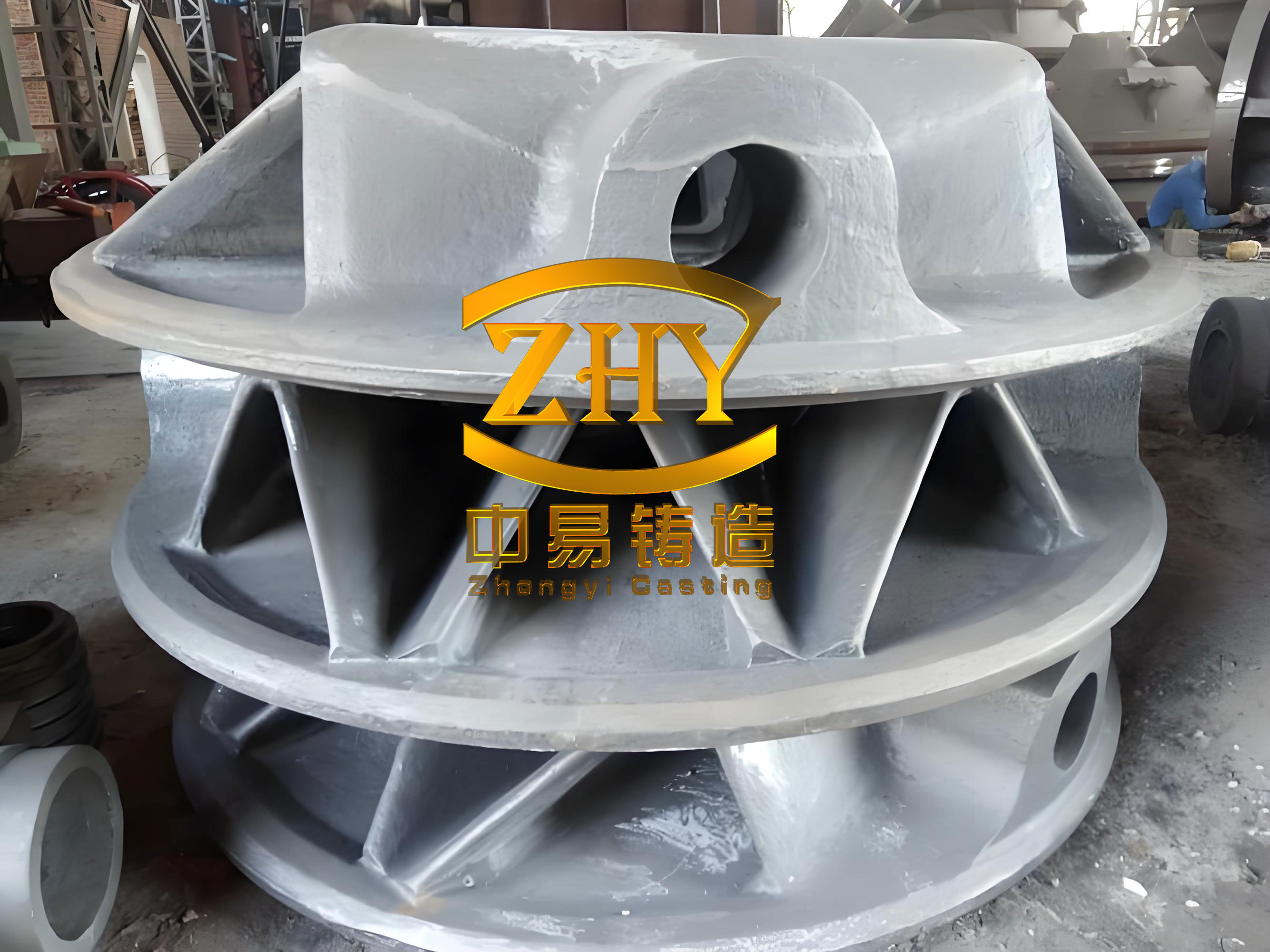
Our project centered on a new variant of a medium-pressure outer cylinder for an ultra-supercritical steam turbine. The component is a quintessential large ductile iron casting, with the key characteristics detailed in Table 1. The material specification was a high-silicon molybdenum ductile iron (akin to QT400-18 or similar enhanced grades), chosen for its excellent high-temperature strength, oxidation resistance, and growth resistance—critical properties for supercritical steam service.
| Characteristic | Value | Remarks |
|---|---|---|
| Overall Dimensions (L x W x H) | 5485 mm x 4320 mm x 2150 mm | Drum-shaped shell structure |
| Poured Weight | ~62,000 kg | Indicative of the massive scale |
| Material | High-Si-Mo Ductile Iron | e.g., QTRSi3Mo or equivalent |
| Flange Wall Thickness | Up to 380 mm | Significant thermal mass |
| Main Cylinder Wall Thickness | 65 – 100 mm | Variable section |
| Nozzle/Port Wall Thickness | ~190 mm |
The new design was an evolution of a previous model. The core “drum” structure, major flanges, and bearing housings remained identical. The primary modifications were in the arrangement of extraction ports on the lower half: the original three ports were reconfigured into four. This involved adding two new ports in diagonally opposite locations and removing one central port, which was replaced with a small reinforcing pad (boss). This presented a classic low-volume production dilemma: fabricating an entirely new set of full-scale patterns for a single casting was financially untenable and would have extended the lead time by several months. Conversely, attempting to modify the existing expensive wooden patterns physically would have been destructive, compromising their future use for the original design. The hybrid 3DSP approach provided an elegant solution.
The established casting process for the original cylinder half employed a three-part mold (drag, intermediate cope, and top cope) split at the main horizontal joint flange. The extensive internal cavity was formed by a single, massive core, with smaller separate cores for the bearing pockets. The gating system was a bottom-filling, ceramic-lined design to ensure smooth, tranquil metal flow into the large cavity. The challenge was to adapt this process to accommodate the new four-port geometry without altering the main pattern or the core box for the large central cavity core.
The devised “3D Printing + Traditional Mold” strategy decomposed the problem based on the nature of the changes:
1. Addition of Two Diagonal Extraction Ports:
For the two new ports, the external contour needed to be added to the drag mold, and the internal sand core defining the port’s interior had to be added to the main core assembly.
- Mold Modification: The external shape of the new ports was created as separate expendable polystyrene (EPS) foam patterns. These foam positives were precisely machined and designed with locators to key into pre-existing or slightly modified areas of the large wooden drag pattern. This was a low-cost, non-destructive way to modify the mold cavity.
- Core Assembly Modification: The internal cores for these new ports were ideal candidates for 3D printing. Their complex, cored-out shapes would be difficult and expensive to make as traditional core boxes for a single use. Two 3D printed sand cores were designed for each port (due to printer bed size limitations), featuring interlocking “step-and-repeat” locators. The lower printed core incorporated a sloped locating surface to ensure precise positioning within the main core assembly. The main core box was also adapted using EPS foam blocks to create negative cavities (core prints) that would accept the locators of these new 3D printed cores.
2. Removal of Central Port & Addition of Boss:
The deleted central port left a void in the main core that needed to be filled, and the new boss needed to be formed.
- We designed a single, complex 3D printed sand core that served a dual purpose: it plugged the hole in the main core corresponding to the old port, and it simultaneously formed the geometry of the new reinforcing boss on the casting’s interior surface. This printed “plug-and-boss” core was designed with locators to seat into the upper mold (cope) during assembly. The corresponding core print in the main core box was filled with an EPS block.
The synergy of these methods is summarized in Table 2, contrasting the traditional approach with the implemented hybrid strategy.
| Aspect | Traditional Full-Tooling Approach | Hybrid “3D Printing + Traditional Mold” Approach |
|---|---|---|
| Tooling Lead Time | 12-16 weeks for new patterns & core boxes | 3-4 weeks (3D model prep & print time, minor EPS patterns) |
| Tooling Cost | Exceptionally High (Full wooden/metal patterns) | Dramatically Reduced (Leverages existing tooling, adds only printed cores/EPS) |
| Design Flexibility | Very Low (Physical modification is difficult/costly) | Very High (Digital changes to printed cores are trivial) |
| Risk to Legacy Tooling | High if physically modified | Minimal to None (Existing patterns remain unaltered) |
| Suitability for Low Volume | Poor | Excellent |
The implementation required meticulous process control, with a focus on dimensional accuracy and core assembly integrity. A critical step was the verification of the composite tooling. After attaching the EPS patterns to the main drag and modifying the core box, we used optical scanning (photogrammetry or structured light) to create a 3D point cloud of the actual tooling. This was compared digitally to the master CAD model, ensuring all locators and geometries were within tolerance before any sand was poured or printed.
The 3D printed cores were designed with integral lifting points and extensive venting channels. The venting is crucial for large sand cores, especially thick printed sections, to allow gases from the binder pyrolysis to escape during pouring, preventing bubble defects. The vent design can be related to the permeability of the printed sand and the rate of gas generation. A simplified relation for ensuring adequate venting area (A_v) can be considered:
$$ A_v \propto \frac{V_c \cdot \rho_b \cdot R_g}{P_a \cdot t_p} $$
Where \( V_c \) is the core volume, \( \rho_b \) is the binder density, \( R_g \) is the gas generation rate of the binder, \( P_a \) is the allowable back-pressure in the mold cavity, and \( t_p \) is the pouring time. For 3D printed cores, the internal vent channels are digitally integrated and guaranteed, unlike sometimes unreliable manually created vents in traditional cores.
The assembly of the main core was a carefully orchestrated operation. The large traditional core was produced in its box. The 3D printed port cores were then lowered and seated into their respective EPS print locations on the main core. Their alignment was verified using portable measurement arms. Finally, the large “plug-and-boss” core was placed into the upper mold section. The mold closure was a critical phase, ensuring the hanging core aligned perfectly with the cavity formed by the EPS patterns on the drag. The gating system remained unchanged from the proven baseline, utilizing a bottom-gate design to fill the massive cavity smoothly. The filling time and gating dimensions were calculated based on the Bernoulli and continuity equations, fundamental to fluid flow in casting:
$$ v = \sqrt{2gh} $$
$$ Q = A \cdot v = A \cdot \sqrt{2gh} $$
Where \( v \) is the theoretical metal velocity at the gate, \( g \) is gravity, \( h \) is the metallostatic head, \( Q \) is the volumetric flow rate, and \( A \) is the total choke area. For a ductile iron casting of this size, a slow, controlled fill is paramount to avoid mold erosion and turbulence, which can lead to dross entrainment and slag defects.
Quality control for such a critical component was multi-faceted. Dimensional inspection was performed at the rough-machined stage using laser trackers, comparing the casting to the digital model. The results confirmed that the hybrid approach successfully maintained the CT13/CT14 tolerances required. The metallurgical quality was paramount. The high-silicon molybdenum ductile iron casting required specific thermal analysis during solidification to ensure the desired microstructure—predominantly ferritic with a stable carbide-free matrix. The solidification time for a section can be estimated using Chvorinov’s Rule:
$$ t_s = B \cdot \left( \frac{V}{A} \right)^n $$
Where \( t_s \) is the solidification time, \( V \) is the volume of the casting section, \( A \) is its surface area, \( n \) is an exponent (often ~2), and \( B \) is a mold constant. The modulus \( \frac{V}{A} \) is critical. For the thick flange sections (up to 380mm), the modulus is very high, leading to long solidification times and a high risk of graphite degradation or intercellular carbides. This was managed through a carefully designed cooling schedule and the use of inoculants and alloying elements to promote graphite nodulization and suppress undesirable phases. Non-Destructive Testing (NDT) was comprehensive. Ultrasonic Testing (UT) per stringent standards (like EN 12680-3) was applied to all highly stressed areas. The soundness of the casting, particularly in the regions adjacent to the new 3D printed core interfaces, was found to be Level 2 for critical zones and Level 4 or better elsewhere, fully meeting specifications. Magnetic Particle Inspection (MT) over the entire surface revealed no significant defects.
The success of this project underscores several key advantages of the hybrid manufacturing methodology for large, complex ductile iron castings:
- Cost and Time Efficiency: The avoidance of new hard tooling for the entire casting saved approximately 70-80% in tooling costs and reduced the development-to-cast lead time by over 60%. This makes prototyping and low-volume production of massive components economically viable.
- Preservation of Legacy Assets: The existing, valuable pattern equipment for the base product variant remained completely intact and undamaged, ready for future production runs of the original design.
- Unprecedented Flexibility: Design changes are encapsulated in digital core files, allowing for rapid iterations. If the customer requested a return to three ports or a different configuration, it would simply involve printing a new set of cores, offering immense agility.
- Geometric Freedom: 3D printing enabled the production of the complex “plug-and-boss” core as a single piece, which would have been extremely challenging to craft or assemble from traditional core segments.
Looking forward, the integration of 3D printing into foundry practice extends beyond hybrid tooling. The technology enables topological optimization of casting designs for lightweighting, integration of conformal cooling channels, and consolidation of multiple parts into single castings. The ability to simulate the entire process—filling, solidification, stress—and then directly manufacture the optimized mold is a powerful closed-loop system. For ductile iron castings, controlling cooling rates in critical sections is vital to achieve the correct ferrite/pearlite ratio and nodule count. Simulation software solves the heat transfer equation during solidification:
$$ \rho C_p \frac{\partial T}{\partial t} = \nabla \cdot (k \nabla T) + \dot{q}_{latent} $$
Where \( \rho \) is density, \( C_p \) is specific heat, \( T \) is temperature, \( t \) is time, \( k \) is thermal conductivity, and \( \dot{q}_{latent} \) is the latent heat source term from the liquid-solid phase change. By validating these simulations against the successful casting, the process knowledge is codified and can be reliably applied to future, even more ambitious projects.
In conclusion, the application of a strategic “3D Printing + Traditional Mold” hybrid approach for the rapid development of a supercritical turbine medium-pressure outer cylinder stands as a testament to the evolving nature of heavy industry. It successfully addressed the economic and logistical challenges of low-volume production for a massive, high-integrity ductile iron casting. This case study demonstrates that additive manufacturing is not merely a replacement for traditional foundry methods but a powerful complementary technology. By fusing digital flexibility with the robustness of conventional casting processes, manufacturers can achieve unprecedented levels of responsiveness, cost-effectiveness, and innovation in producing the large, complex components that power modern infrastructure. The future of heavy casting lies in this intelligent synergy, pushing the boundaries of what is possible in metal fabrication.