
The demand for reliable, high-integrity castings in critical applications like wind energy has driven significant advancements in foundry technology. Among these, the production of **ductile iron casting** parts capable of withstanding extreme environmental conditions, particularly low temperatures, represents a pinnacle of metallurgical and process control. My focus here is on sharing a comprehensive, first-hand perspective on mastering the **lost foam casting** process specifically for manufacturing large, complex components such as wind turbine motor end covers from low-temperature, high-toughness ductile iron. This process integrates meticulous pattern engineering, rigorous metallurgical discipline, and precise thermal management to achieve properties that meet stringent international standards.
The core challenge lies in producing a **ductile iron casting** with a fully ferritic matrix, exceptionally high impact toughness at sub-zero temperatures (e.g., -20°C or -40°C), and flawless surface quality free from defects like shrinkage, slag inclusions, or distortion. Traditional green sand or resin sand methods are common, but the lost foam process offers distinct advantages for complex geometries, dimensional accuracy, and reduced cleaning effort. However, it introduces its own set of variables that must be meticulously controlled to achieve the desired metallurgical structure and mechanical performance in a **ductile iron casting**.
1. The Lost Foam Process: A Blueprint for Precision
The journey of a perfect **ductile iron casting** begins long before metal is poured. In lost foam casting, the polymer pattern is the literal blueprint, and its integrity dictates the final part’s dimensional fidelity.
1.1 Pattern Fabrication and Assembly
For components like motor end covers, expanded polystyrene (EPS) sheets with a controlled density of approximately 18 kg/m³ are selected. This density offers an optimal balance between pattern strength for handling and minimal gaseous decomposition products during casting. The pattern, including all complex ribs and mounting features, is precision-cut and assembled. The gating and feeding system—crucial for soundness—is also constructed from the same density EPS and seamlessly attached to the component pattern. A key design principle is to ensure rapid, tranquil filling to replicate thin sections like cooling fins accurately. Computer simulation (e.g., using software like ProCAST) is indispensable for optimizing the feeding system, predicting solidification patterns, and eliminating potential shrinkage zones before any physical pattern is made.
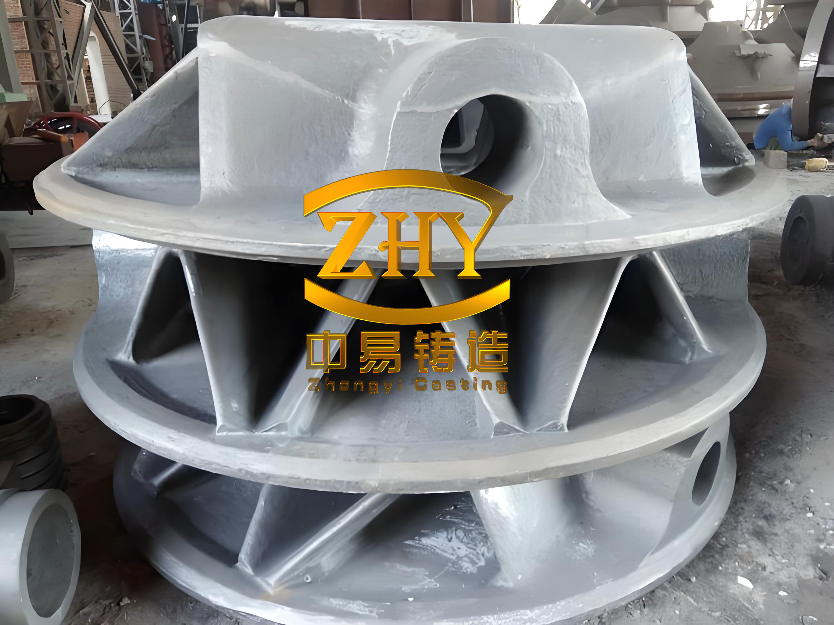
1.2 Coating Application and Drying: Building the Interface
The EPS pattern is coated with a refractory slurry that forms the critical barrier between the decomposing foam and the molten metal. For this **ductile iron casting** application, a specialized water-based quartz flour coating is used. The process is multi-stage:
- First Coat: Applied at a lower density (e.g., Baume 1.6) to ensure good penetration into fine pattern details. Drying time ≥ 12 hours.
- Subsequent Coats (2-3): Applied at a higher density (Baume 1.7-1.8) to build up a total thickness of 1.2-1.5 mm, ensuring adequate refractory strength and gas permeability. Drying time ≥ 20 hours per coat.
Patterns must be handled carefully during coating and drying, supported at sturdy points like the sprue base to prevent distortion. Drying occurs in a controlled environment (~50°C, ~18% humidity). A core rule is to monitor weight; the pattern is considered dry only when its weight stabilizes over a 4-hour interval. Crucially, fully dried patterns ready for molding must be stored separately from newly coated ones to prevent moisture absorption.
1.3 Molding and Compaction
The dried, coated pattern (now called the “cluster”) is placed in a flask on a base layer of dry, unbonded silica sand. Sand is then carefully introduced around the cluster using a fill-sand system, accompanied by controlled vibration to achieve uniform and adequate compaction. The vibration must be sufficient to ensure flowability around intricate features but not so aggressive as to cause pattern deformation or coating damage. A key practice is creating numerous small vent holes (e.g., 4 mm diameter) in the cope (top) section of the mold above thin ribs to facilitate the rapid escape of decomposition gases, preventing incomplete filling or cold shuts. The sprue cup area is often reinforced to prevent erosion during pouring. The entire mold is then placed under a vacuum, which consolidates the sand and extracts gases from the foam degradation during the pour.
2. Metallurgical Mastery for Low-Temperature Toughness
The heart of a superior low-temperature **ductile iron casting** is its chemistry and microstructure. The goal is a ferritic matrix with a high count of small, well-nodularized graphite spheres, and minimal impurities.
2.1 Foundry Raw Material Philosophy
The selection of charge materials is non-negotiable. High-purity pig iron (e.g., Q10/Q12 grades) with very low levels of trace elements (particularly Mn, P, and S) forms the base. Steel scrap should be clean, low-carbon, and low-manganese. The objective is to keep the base iron as “clean” as possible. The choice of inoculant and nodularizer is equally critical:
| Material | Key Requirement | Purpose & Rationale |
|---|---|---|
| Pig Iron | Low Mn (<0.2%), Low P (<0.05%), Low S (<0.02%) | Minimizes carbide formation, avoids brittle phosphide eutectics, reduces nodularizer consumption. |
| Steel Scrap | Low Mn (<0.3%), Unoxidized | Prevents excessive Mn pickup; ensures predictable carbon dissolution. |
| Nodularizer | Low-Mg, Low-RE, Yttrium-Base (e.g., ~6%Mg, ~2%RE) | Promotes stable, uniform nodularization without excessive oxide/sulfide dross formation. Targets final residuals: Mgres ~0.04-0.05%, REres ~0.03-0.04%. |
| Inoculant | Ferritic, Long-Lasting Type (e.g., Si-Ba-Ca-Bi) | Promotes a high graphite nodule count, refines graphite structure, supports ferrite formation. Used in multiple stages. |
2.2 Chemical Composition: The Precise Formula
Each element plays a specific role, and its concentration is a carefully balanced act. The target composition for a QT400-18AL/EN-GJS-400-18U-LT grade **ductile iron casting** is summarized below:
| Element | Target Range (wt.%) | Metallurgical Rationale & Control Strategy |
|---|---|---|
| Carbon (C) | 3.65 – 3.90 | High carbon improves graphitization potential and fluidity but must be balanced against graphite floating. Often achieved via recarburization using high-purity graphite. |
| Silicon (Si) | 2.10 – 2.40 | A powerful graphitizer. Must be controlled tightly; levels >2.4% can significantly reduce low-temperature impact toughness. Final Si is a sum of base iron, nodularizer, and inoculant additions. |
| Manganese (Mn) | < 0.20 | A strong pearlite promoter that segregates at cell boundaries. “The lower, the better” for maximum ferrite content and toughness. |
| Phosphorus (P) | < 0.04 | Forms hard, brittle phosphide networks at grain boundaries, severely degrading ductility and impact strength. Must be minimized via raw material selection. |
| Sulfur (S) | < 0.025 | Consumes magnesium to form MgS slag. Low base S ensures efficient, predictable nodularization. |
| Nickel (Ni) | 0.3 – 0.6 | Added to enhance low-temperature toughness and stabilize ferrite without forming carbides. |
| Mgres | 0.04 – 0.05 | Ensures sustained nodularizing effect throughout solidification. |
| REres | 0.03 – 0.04 | Counteracts trace element interference but kept low to prevent graphite spiking or compacted forms. |
The relationship between silicon content and low-temperature impact toughness can be conceptually viewed as needing optimization. While a precise predictive formula is complex, the inverse relationship guides practice:
$$ \text{Impact Toughness}_{(-20^\circ C)} \propto \frac{1}{[Si]^n} $$
where ‘n’ is a positive exponent, emphasizing that excessive silicon is detrimental.
2.3 Melting, Nodularization, and Inoculation: The Critical Sequence
Melting is typically performed in medium-frequency induction furnaces for superior temperature and chemistry control. The base iron chemistry is adjusted to: C: 3.65-3.9%, Si: 1.1-1.3%, Mn<0.2%, P<0.05%, S<0.03%. The nodularization treatment employs the sandwich method in a preheated ladle. The calculated amount of nodularizer (1.2-1.45%) is placed in the bottom, covered with steel punchings, and then treated with hot metal at 1480-1500°C.
Inoculation is performed in two decisive stages to maximize graphite nucleation:
- Ladle Inoculation: Immediately after the nodularizing reaction, a ferritic-type inoculant (e.g., 0.6-0.7% of ladle weight) is added to the metal stream as the ladle is topped up.
- Stream Inoculation: During pouring, a fine-grained (0.2-0.8 mm), potent inoculant (e.g., containing Bi) is added at a rate of ~0.25% into the metal stream at the pouring basin. This late inoculation creates instant, highly effective nucleation sites.
The effectiveness of inoculation can be related to the resulting graphite nodule count ($N$), a critical parameter for toughness:
$$ N \propto I_{eff} \cdot \exp\left(-\frac{Q}{\Delta T}\right) $$
where $I_{eff}$ is the inoculation efficiency factor (dependent on inoculant type and method), $Q$ is an activation energy term, and $\Delta T$ is the undercooling. Effective double inoculation maximizes $I_{eff}$ and refines the structure.
2.4 Pouring and Solidification
Pouring temperature is maintained between 1400-1430°C. A rapid, non-turbulent pour is essential to ensure complete filling of thin sections before the foam degradation gases chill the metal. The mold’s negative pressure is maintained throughout pouring and the initial solidification phase to hold the shape and evacuate gases. The slow cooling inherent in the unbonded sand mold of the lost foam process is actually beneficial for this **ductile iron casting**, promoting the desired ferritic transformation:
$$ \frac{dT}{dt}_{sand} \propto \frac{1}{x^2} $$
where $dT/dt$ is the cooling rate and $x$ is the mold wall thickness (effectively the sand mass around the casting). A slower cooling rate through the eutectoid transformation range favors the diffusion-dependent formation of ferrite over pearlite.
3. Post-Casting Thermal Treatment
Even with optimal chemistry and processing, the as-cast **ductile iron casting** may contain minor amounts of carbides or pearlite, especially in varying section thicknesses. A ferritizing annealing heat treatment is therefore standard to guarantee >95% ferrite and maximum toughness.
The thermal cycle involves:
- Heating to 910-940°C and holding for 2-5 hours. This dissolves any carbides (cementite, Fe3C) into austenite ($\gamma$):
$$ \text{Fe}_3\text{C} + \gamma_{(low-C)} \rightarrow \gamma_{(high-C)} $$ - Slow cooling or furnace cooling to the eutectoid range (~720-740°C) and holding for 3-6 hours. This extended soak allows carbon to diffuse from the austenite to existing graphite nodules, forming a carbon-depleted austenite that transforms to ferrite ($\alpha$) upon cooling:
$$ \gamma_{(high-C)} \rightarrow \alpha + \text{Graphite} $$ - Final cooling to below 580°C, after which the casting can be air-cooled.
4. Quality Validation and Results
The final validation of the process lies in the measurable properties of the **ductile iron casting**. For wind turbine end covers, 100% non-destructive testing (ultrasonic) of machined surfaces is performed. The mechanical properties and microstructure, typically checked on separately cast or attached test bars, must meet or exceed specifications.
| Property / Metric | Standard Requirement (e.g., EN-GJS-400-18U-LT) | Typical Achieved Result |
|---|---|---|
| Tensile Strength, Rm | > 400 MPa | 415 – 425 MPa |
| Yield Strength, Rp0.2 | > 240 MPa | 250 – 280 MPa |
| Elongation, A | > 18 % | 21 – 26 % |
| Impact Energy, KV (-20°C) | > 12 J | 16 – 19 J |
| Hardness, HB | – | 145 – 155 |
| Microstructure | > 90% Ferrite, No Carbides/Phosphides | 95 – 97% Ferrite, No Carbides/Phosphides |
| Graphite Nodularity | > 90% (Type I, II) | > 92% (Type I) |
| Graphite Nodule Count | – | 120 – 180 nodules/mm² |
The high nodule count is a direct result of effective inoculation and is a fundamental contributor to the high toughness. The relationship between nodule count ($N$), ferrite fraction ($F$), and impact toughness ($IT$) can be conceptually summarized as aiming for:
$$ IT_{(-20^\circ C)} = k \cdot F \cdot \sqrt{N} $$
where $k$ is a material constant, indicating that maximizing both ferrite content and graphite nodule count synergistically improves low-temperature performance.
5. Conclusion
The successful production of low-temperature, high-toughness **ductile iron casting** components like wind turbine motor end covers via the lost foam process is a testament to integrated process engineering. It requires a holistic approach where pattern design and coating integrity are as critical as metallurgical purity and thermal management. By selecting ultra-low impurity raw materials, employing a low-RE/Mg nodularizer, implementing a rigorous double inoculation practice, and following a precise ferritizing anneal, the target microstructure—a high-count, well-nodularized graphite in a >95% ferritic matrix—is reliably achieved. The lost foam process itself, with its superior dimensional replication and reduced cleaning needs, proves to be a highly viable and efficient method for serial production of such demanding castings. The final **ductile iron casting** exhibits not only exceptional mechanical properties, including guaranteed low-temperature impact values, but also excellent surface quality, free from defects like sand inclusion, slag, or cold shuts, making it fully capable of meeting the rigorous demands of renewable energy applications. This synthesis of advanced casting technique and precise metallurgical science defines the modern standard for high-performance **ductile iron casting**.