
In the realm of advanced materials, ductile iron casting represents a critical class of engineering components due to its exceptional mechanical properties, including high strength, ductility, fatigue resistance, and wear resistance. Among these, austempered ductile iron (ADI), a specific type of ductile iron casting subjected to an isothermal quenching process, has garnered significant attention for applications in heavy-duty industries such as automotive, rail transport, and machinery. The production of thick-walled austempered ductile iron castings, however, is inherently prone to the formation of internal discontinuities like shrinkage porosity, gas pores, and inclusions. These defects can compromise the structural integrity and performance of the component, necessitating reliable nondestructive testing (NDT) methods for quality assurance. This study, from my perspective as a researcher involved in this field, aims to comprehensively compare and analyze various NDT techniques applied to thick-walled ductile iron casting workpieces with wall thicknesses ranging from 60 mm to 135 mm. The focus is on evaluating the sensitivity and reliability of these methods for detecting cavity-type defects.
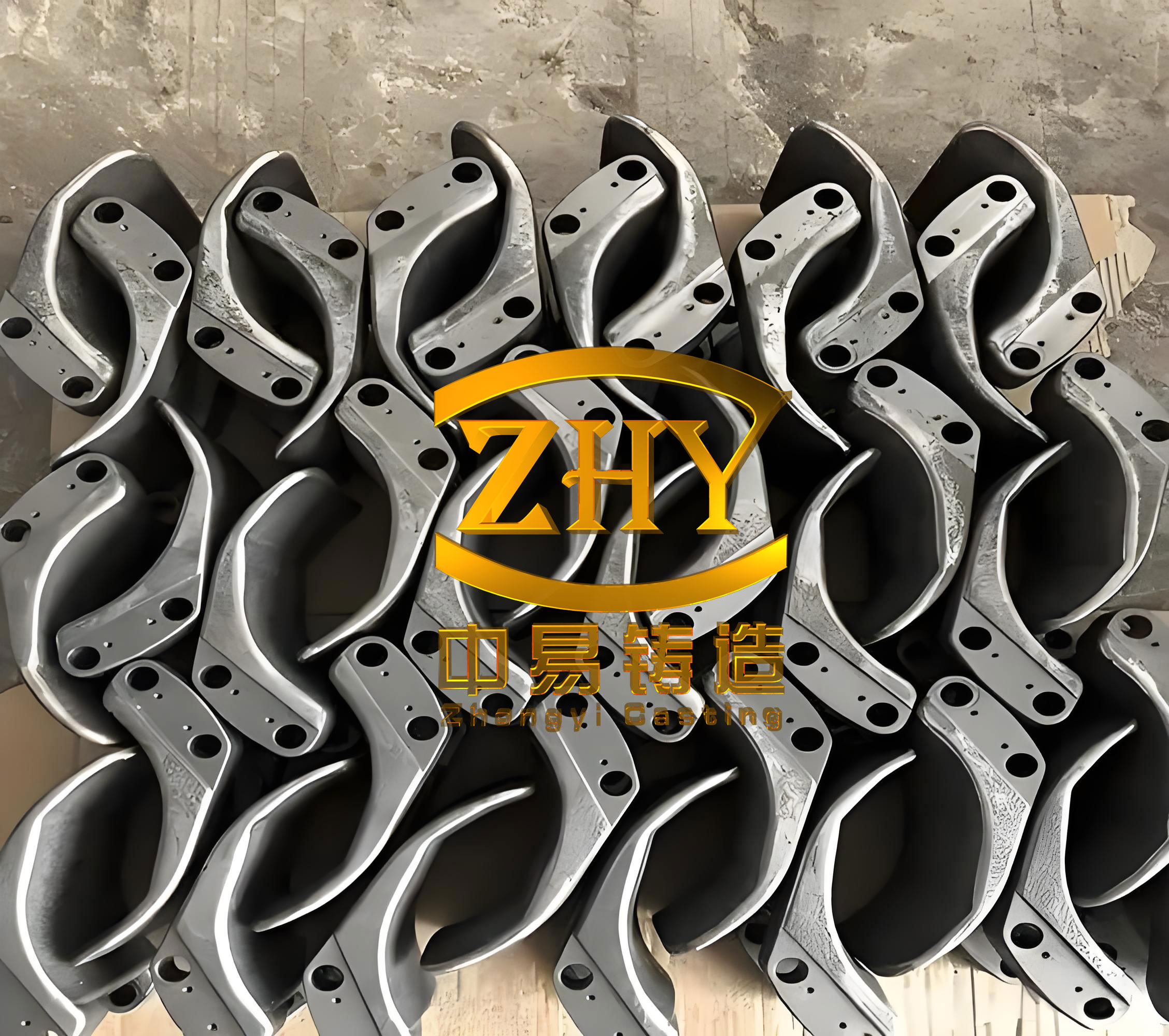
The inherent challenges in inspecting thick-walled ductile iron casting components are multifaceted. Conventional X-ray radiography often lacks sufficient penetration capability, while high-energy radiation sources like Co-60 or high-energy X-rays, though penetrative, may suffer from reduced image contrast and sensitivity, making small defect detection difficult. Furthermore, the ultrasonic inspection of ductile iron casting materials, particularly austempered varieties, is not extensively documented. The material’s coarse microstructure can lead to significant ultrasonic scattering, attenuation, and high background noise, potentially masking defect signals. Therefore, a systematic investigation was undertaken to assess the efficacy of several NDT methodologies: conventional ultrasonic testing (UT), phased array ultrasonic testing (PAUT), gamma-ray radiography, and high-energy X-ray digital radiography. This evaluation is crucial for establishing robust inspection protocols for ductile iron casting products used in safety-critical applications.
The fundamental principle behind ultrasonic testing involves the generation and reception of high-frequency sound waves. When these waves encounter an interface, such as a defect within a ductile iron casting, part of the energy is reflected back to the probe. The amplitude of this reflected signal can be related to the size of the reflector. For flat-bottomed holes (FBH), a common reference reflector, the reflected pressure amplitude at a given distance can be described by a simplified formula derived from the ultrasonic wave equation. The sound pressure from a circular piston probe at a distance \(x\) for a FBH of diameter \(D\) can be approximated as:
$$ P(x) = P_0 \frac{A}{\lambda x} \cdot \frac{D^2}{4x} \cdot e^{-\alpha x} $$
where \(P_0\) is the initial pressure, \(A\) is the probe area, \(\lambda\) is the wavelength, \(\alpha\) is the attenuation coefficient, and \(x\) is the sound path. The attenuation in ductile iron casting is notably high due to its graphite nodule morphology, which scatters ultrasound. The attenuation coefficient \(\alpha\) can be modeled as a function of frequency \(f\) and microstructure parameters. For ductile iron casting with spheroidal graphite, an empirical relation is often used:
$$ \alpha = \alpha_0 + \beta f^n $$
where \(\alpha_0\), \(\beta\), and \(n\) are material-dependent constants. This scattering loss directly impacts the signal-to-noise ratio (SNR), a critical factor in defect detectability. To quantify detection capability, the concept of an equivalent reflector size (e.g., FBH diameter) is used. The detectability condition can be expressed as:
$$ 20 \log_{10}\left( \frac{V_{defect}}{V_{noise}} \right) \ge \Delta_{TH} $$
where \(V_{defect}\) is the voltage amplitude from the defect, \(V_{noise}\) is the root-mean-square noise level, and \(\Delta_{TH}\) is the threshold signal-to-noise ratio, typically 6 dB to 12 dB for reliable detection.
In this study, the initial verification of ultrasonic inspectability for the thick-walled ductile iron casting was performed using a \(\Phi 3\) mm FBH. A signal exceeding the background noise by more than 12 dB confirmed adequate penetration and probing capability. Building upon guidelines similar to GB/T 34904-2017, three distinct approaches for setting the detection sensitivity in conventional UT were formulated and compared, as summarized in the table below.
| Sensitivity Setting Method | Probe Type | Reference Reflector | Quantification Principle | Mathematical Representation |
|---|---|---|---|---|
| Equivalent AVG/DGS | Single Crystal, Straight Beam | \(\Phi 1\) mm or \(\Phi 2\) mm FBH | Read absolute equivalent size (ΦX mm) | $$ G = G_0 \left( \frac{D_{ref}^2}{D_x^2} \right) \left( \frac{x_{ref}}{x} \right)^2 e^{-2\alpha (x – x_{ref})} $$ where \(G\) is gain, \(D\) is diameter, \(x\) is distance. |
| DAC Curve | Single or Twin Crystal, Straight Beam | \(\Phi 2\) mm or \(\Phi 5\) mm FBH | Read signal amplitude relative to DAC curve (e.g., DAC ± Y dB) | $$ A_{DAC}(x) = A_{ref} \cdot \left( \frac{x_{ref}}{x} \right)^2 \cdot e^{-2\alpha (x – x_{ref})} $$ Defect reported if \(A_{defect} \ge A_{DAC}(x) \cdot 10^{(Y/20)}\). |
| Background Noise Limit | Single or Twin Crystal, Straight Beam | N/A | Monitor signals >6 dB above averaged noise floor | $$ A_{defect} > \mu_{noise} + k \cdot \sigma_{noise} $$ where \(\mu_{noise}\) is mean noise, \(\sigma_{noise}\) is standard deviation, \(k\) is factor (e.g., corresponding to 6 dB). |
The DAC curve was constructed using a reference block containing FBHs at various depths, specifically designed for this ductile iron casting evaluation. During scanning, several distinct signal types were observed in the thick-walled ductile iron casting specimens. In sound areas, a high-amplitude backwall echo with low background noise was prevalent. In regions containing small, discrete defects, distinct flaw signals with amplitudes corresponding to equivalent FBH sizes from \(\Phi 0.9\) mm to \(\Phi 2\) mm were recorded. In areas suspected of containing gross porosity or clusters of defects (regional defects), a significant reduction in the backwall echo amplitude (\(>12\) dB drop) was the primary indicator, sometimes accompanied by lower-amplitude flaw signals. This backwall echo drop can be modeled by a transmission coefficient for a porous layer. If a defect zone of thickness \(d_{def}\) and acoustic impedance \(Z_{def}\) is present, the pressure transmission coefficient \(T\) to the backwall is:
$$ T = \frac{4 Z_{def} Z_m}{(Z_{def} + Z_m)^2} \cdot e^{-\alpha_{def} d_{def}} $$
where \(Z_m\) is the impedance of the base ductile iron casting material and \(\alpha_{def}\) is the attenuation within the defect zone. A substantial reduction in \(T\) directly correlates to a weaker backwall echo.
Phased array ultrasonic testing represents an advanced evolution of conventional UT, offering electronic scanning, beam steering, and focusing. For the inspection of thick-walled ductile iron casting, a specialized Dual Linear Array (DLA) transducer was employed. This configuration uses separate transmit and receive linear arrays, effectively functioning as an array-version of a twin-crystal probe. This design mitigates the influence of surface waves and near-surface noise, optimizing the beam for defects at a specific depth range within the ductile iron casting. The beam focusing law for a linear array can be calculated using time delays \(\Delta t_i\) for each element \(i\) to focus at a point \((x_f, z_f)\):
$$ \Delta t_i = \frac{1}{c} \left( \sqrt{(x_i – x_f)^2 + z_f^2} – \sqrt{(x_0 – x_f)^2 + z_f^2} \right) $$
where \(c\) is the sound velocity in the ductile iron casting, \(x_i\) is the position of the \(i\)-th element, and \((x_0, z_f)\) is a reference point. The DLA setup allows dynamic depth focusing (DDF), which is particularly beneficial for inspecting the entire volume of a thick-walled ductile iron casting. The synthetic focusing improves the signal-to-noise ratio according to:
$$ SNR_{PA} \approx SNR_0 \cdot \sqrt{N} \cdot F $$
where \(N\) is the number of active elements and \(F\) is a focusing gain factor. The PAUT inspection successfully detected defect indications with equivalent sizes comparable to those found by conventional UT. The sectorial scans and C-scan images provided clearer spatial mapping of the defect locations within the complex geometry of the ductile iron casting workpiece.
Radiographic testing methods rely on the differential absorption of penetrating radiation. For thick-walled ductile iron casting components, gamma-ray sources like Ir-192 and Co-60, as well as high-energy X-rays, are necessary to achieve sufficient penetration. The fundamental law governing radiation intensity attenuation is the Beer-Lambert law:
$$ I = I_0 e^{-\mu T} $$
where \(I_0\) is the initial intensity, \(I\) is the transmitted intensity, \(\mu\) is the linear attenuation coefficient, and \(T\) is the total thickness. For ductile iron casting, \(\mu\) depends on the effective atomic number and density. The presence of a defect (e.g., a pore) of thickness \(d\) within the material creates a local thickness variation \(\Delta T = T – (T – d) = d\). The resulting contrast \(\Delta I\) in the transmitted intensity is:
$$ \Delta I = I_0 e^{-\mu (T-d)} – I_0 e^{-\mu T} = I_0 e^{-\mu T} (e^{\mu d} – 1) $$
For small defects (\( \mu d << 1 \)), this approximates to \( \Delta I \approx I_0 \mu d e^{-\mu T} \). The visibility of this contrast is limited by system unsharpness and noise. The key metric for radiographic sensitivity is the relative sensitivity \(K\), typically measured using a wire-type image quality indicator (IQI):
$$ K = \frac{d_{min}}{T} \times 100\% $$
where \(d_{min}\) is the diameter of the smallest visible wire in the radiograph. The following table details the parameters and results for the gamma-ray and high-energy X-ray inspections conducted on the thick-walled ductile iron casting samples.
| Testing Method | Radiation Source / Energy | Approx. Focal Spot Size | Test Thickness (T) Range | IQI Type & Visible Wire (\(d_{min}\)) | Calculated Relative Sensitivity (K) |
|---|---|---|---|---|---|
| Gamma Radiography | Ir-192 (~0.35 MeV avg) | 3.0 mm × 2.6 mm | 32 mm, 36 mm, 60 mm | ASTM 1B11, Wire #7 (0.33 mm) | $$ K_{32} = \frac{0.33}{32} \times 100\% = 1.03\% $$ $$ K_{36} = \frac{0.33}{36} \times 100\% = 0.92\% $$ $$ K_{60} = \frac{0.81}{60} \times 100\% = 1.35\% $$ |
| Gamma Radiography | Co-60 (~1.25 MeV avg) | 4.0 mm × 4.0 mm | 135 mm | ASTM 1C16, Wire #11 (1.02 mm) or #12 (1.14 mm) | $$ K_{135}^{11} = \frac{1.02}{135} \times 100\% = 0.76\% $$ $$ K_{135}^{12} = \frac{1.14}{135} \times 100\% = 0.84\% $$ |
| High-Energy X-ray Digital Radiography | 9 MeV LINAC | < 2 mm | 135 mm | ASTM 1C16, Wire #14 (1.60 mm) | $$ K_{135}^{9MeV} = \frac{1.60}{135} \times 100\% = 1.19\% $$ |
Despite achieving a relatively high sensitivity value of 0.76% with Co-60 for the 135 mm thick ductile iron casting, the actual radiographs failed to reveal the small defect indications (equivalent to \(\Phi 0.9\) mm to \(\Phi 2\) mm FBH) that were clearly detected by ultrasonic methods. This discrepancy highlights a critical limitation: the IQI sensitivity metric measures the visibility of a high-contrast, isolated wire under ideal conditions, but it does not fully account for the complex noise structure and low contrast of small, volumetric defects like pores within a ductile iron casting matrix. The noise in radiography, especially with high-energy sources, comprises scatter radiation (\(I_s\)) and quantum noise. The signal-to-noise ratio for defect detection in radiography can be expressed as:
$$ SNR_{RT} = \frac{\Delta I}{\sigma_I} \approx \frac{\mu d I_0 e^{-\mu T}}{\sqrt{I_0 e^{-\mu T} (1 + S)}} = \mu d \sqrt{\frac{I_0 e^{-\mu T}}{1 + S}} $$
where \(S\) is the scatter-to-primary radiation ratio. For thick sections of ductile iron casting, \(S\) can be very high, severely degrading \(SNR_{RT}\). The 9 MeV X-ray system, while providing adequate penetration, resulted in an even poorer theoretical sensitivity (1.19%) and likewise did not image the small defects.
To further investigate the radiographic detectability of the larger, regional defect indicated by the ultrasonic backwall echo loss, the thick-walled ductile iron casting sample was sectioned into thinner layers (25-35 mm thick). These layers were then inspected using a 450 kV X-ray digital imaging system. The reduced thickness \(T’\) dramatically improves contrast and SNR, as seen from the formulas above where \(SNR_{RT} \propto e^{-\mu T’/2}\). This inspection successfully identified an area of shrinkage porosity in one 30 mm thick layer, which corresponded precisely to the region where UT showed a drastic backwall echo reduction. This confirms that the defect was a volumetric discontinuity but was radiographically invisible in the full thickness due to contrast limitations.
The comprehensive comparison leads to several definitive conclusions regarding the nondestructive evaluation of thick-walled austempered ductile iron castings. The performance of each method can be quantitatively summarized by defining a minimum detectable defect size parameter \(\delta_{min}\) for a given thickness \(T\). Based on the experimental data, empirical models can be proposed.
For ultrasonic testing (conventional and PAUT) on ductile iron casting, \(\delta_{min}\) is primarily governed by the attenuation and noise floor. A semi-empirical relation can be stated as:
$$ \delta_{min}^{UT}(T) \approx D_0 \cdot e^{\alpha’ T} $$
where \(D_0\) is a constant related to probe sensitivity and reference reflector (e.g., ~0.9 mm from this study), and \(\alpha’\) is an effective attenuation factor for the detection threshold. For the tested ductile iron casting, \(\delta_{min}^{UT}\) remained below 2 mm even at 135 mm thickness.
For radiographic testing (Gamma/X-ray) on ductile iron casting, \(\delta_{min}\) is driven by contrast and noise. A simplified model derived from the contrast equation is:
$$ \delta_{min}^{RT}(T) \approx \frac{C_{sys}}{\mu} \cdot e^{\mu T} $$
where \(C_{sys}\) is a system constant encompassing noise, unsharpness, and detector threshold. The exponential term explains the rapid increase in \(\delta_{min}^{RT}\) with thickness \(T\) for ductile iron casting. The following table provides a consolidated summary of the findings and recommended applications for inspecting ductile iron casting components.
| NDT Method | Effective Thickness Range for Ductile Iron Casting | Minimum Detectable Defect Size (Estimated) | Key Advantages for Ductile Iron Casting | Primary Limitations for Ductile Iron Casting | Recommended Application Scenario |
|---|---|---|---|---|---|
| Conventional Ultrasonic Testing (UT) | Up to ≥ 135 mm | \(\delta_{min} \approx 0.9 – 2.0\) mm FBH equivalent | High sensitivity to small, discrete defects; Can detect regional porosity via backwall echo drop; Portable and quantitative. | Requires couplant; Surface condition sensitive; Attenuation and noise require careful sensitivity setup. | Primary volumetric inspection for thick-walled ductile iron casting forgings and castings. |
| Phased Array Ultrasonic Testing (PAUT) | Up to ≥ 135 mm | \(\delta_{min} \approx 0.9 – 2.0\) mm FBH equivalent | Electronic scanning & focusing improve SNR and imaging; Better defect sizing and visualization; Suitable for complex geometries. | Higher equipment cost; More complex data interpretation. | Volumetric inspection and detailed mapping of defects in critical ductile iron casting components. |
| Gamma Radiography (Ir-192, Co-60) | Ir-192: ~30-100 mm; Co-60: ~50-200 mm (for ductile iron casting) | \(\delta_{min} > ~2-3\) mm for thickness > 60 mm (based on actual defect detection failure) | Good for planar defects; Provides permanent record; Established standards. | Poor sensitivity for small volumetric defects in thick sections; Radiation safety hazards; Low contrast for porosity in ductile iron casting. | Supplementary inspection for gross defects or planar flaws when UT access is limited; Better for thinner sections. |
| High-Energy X-ray Digital Radiography (9 MeV) | > 100 mm | \(\delta_{min} > ~3\) mm for 135 mm thick ductile iron casting | Excellent penetration for very thick sections; Digital imaging allows processing. | Low contrast sensitivity; High cost; Large facility required. | Penetration of extremely thick ductile iron casting assemblies where UT is not feasible, but with limited sensitivity to small defects. |
| Medium-Energy X-ray Digital Radiography (450 kV) | Up to ~50 mm (for ductile iron casting) | \(\delta_{min} \approx 1 – 2\) mm for ~30 mm thickness | Good contrast for porosity in moderate thicknesses; Digital imaging. | Limited penetration for thick-walled ductile iron casting. | Inspection of sectioned samples or thin-walled regions of ductile iron casting components. |
In conclusion, for the nondestructive inspection of thick-walled austempered ductile iron castings in the 60 mm to 135 mm wall thickness range, ultrasonic methods—both conventional and phased array—emerge as the superior and recommended techniques. They provide the necessary sensitivity to detect critical defect sizes down to approximately \(\Phi 0.9\) mm equivalent flat-bottomed hole diameter, along with the capability to identify regions of gross porosity through backwall echo attenuation analysis. The successful application of these methods requires a deep understanding of the ultrasonic properties of ductile iron casting, such as attenuation and velocity, and the implementation of optimized sensitivity setting procedures, including DAC curves and noise-based thresholds. Radiographic methods, while useful for other material forms or defect types, exhibit fundamental limitations in contrast-to-noise ratio when applied to small volumetric defects within thick sections of ductile iron casting. Therefore, a combined approach utilizing conventional UT for initial scanning and PAUT for detailed characterization is proposed as the most effective quality assurance strategy for ensuring the reliability and safety of high-performance thick-walled ductile iron casting components in demanding engineering applications.