
In the field of heavy-duty industrial equipment, ductile iron castings play a pivotal role due to their exceptional mechanical properties, such as high strength and ductility. As an engineer specializing in foundry technology, I have extensively studied the casting processes for large components like sand suction pump bodies. These ductile iron castings are critical in applications such as river dredging and land reclamation, where they endure harsh environments with abrasive media. This article delves into the intricate casting process of a ductile iron sand suction pump body, sharing insights from my firsthand experience in designing and implementing robust manufacturing techniques. The focus is on overcoming challenges like shrinkage defects and ensuring high-quality ductile iron castings through meticulous process control.
The pump body in question is a massive ductile iron casting weighing 46,600 kg, with dimensions of 5,800 mm × 3,480 mm × 2,200 mm. Its wall thickness varies from 75 mm to 355 mm, and it is made of QT500-7 ductile iron. The irregular shape and stringent quality requirements, such as freedom from porosity in threaded holes for pump cover assembly, make this ductile iron casting particularly challenging. To address this, we adopted an expanded polystyrene (EPS) mold casting process, commonly known as lost-foam casting, combined with furan resin sand. This approach simplifies mold design by eliminating draft angles and parting lines, but it introduces issues like poor surface finish due to low sand compaction. In my practice, I have found that optimizing the gating system, using chills, and implementing effective risering are key to producing sound ductile iron castings.
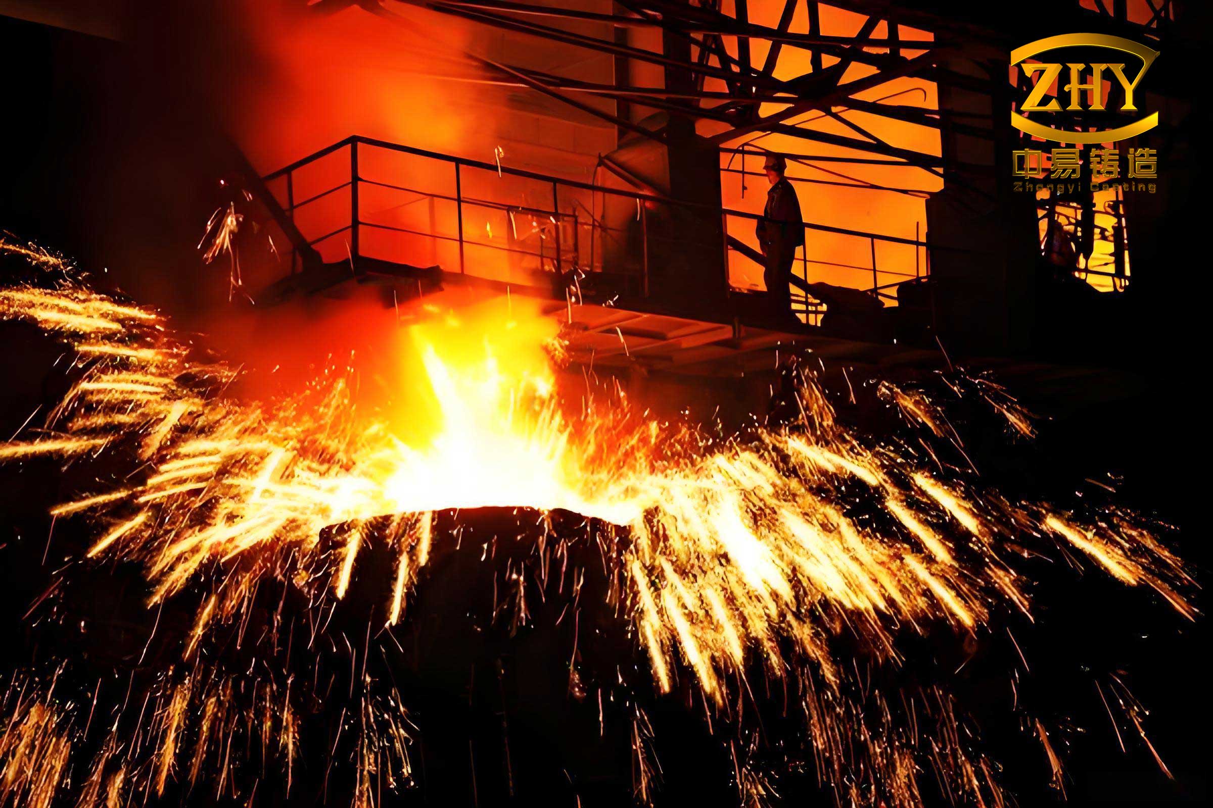
In the mold preparation phase, the EPS pattern is crafted to match the final ductile iron casting geometry, with allowances for machining and shrinkage. We typically use a shrinkage rate of 0.8% to 1.0% for ductile iron castings. The pattern is segmented into modules for precision CNC machining and wire cutting, then assembled and coated with graphite paint to enhance surface quality. This method ensures dimensional accuracy but requires careful handling to prevent sand inclusion defects. For the gating system, we designed a bottom-pouring two-tier step gating system to facilitate smooth filling and reduce turbulence. The hydraulic head is calculated using the formula:
$$H_p = H_{\text{flask}} + H_{\text{pour cup}} – \frac{C}{2}$$
where \(H_p\) is the metal pressure head, \(H_{\text{flask}}\) is the flask height, \(H_{\text{pour cup}}\) is the pouring cup height, and \(C\) is the casting height. The pouring time is determined by:
$$t = \sqrt[3]{G_L}$$
with \(t\) as pouring time in seconds and \(G_L\) as pouring weight in kg. The choke area \(A_{\text{choke}}\) is derived from:
$$A_{\text{choke}} = \frac{G_L}{\mu \rho \sqrt{2g H_p}}$$
where \(\mu\) is the flow coefficient (typically 0.4 for ductile iron castings), \(\rho\) is the density of ductile iron (7.3 kg/mm³), and \(g\) is gravitational acceleration (9.8 m/s²). For this ductile iron casting, we used three ladles for pouring, with calculated areas for sprue, runner, and ingate. Table 1 summarizes the gating system parameters.
| Component | Calculated Area (mm²) | Revised Area (mm²) | Dimensions |
|---|---|---|---|
| Sprue (\(A_{\text{sprue}}\)) | Based on \(A_{\text{choke}}/0.8\) | 1,200 | Φ40 mm |
| Runner (\(A_{\text{runner}}\)) | \(A_{\text{sprue}} \times 1.2\) | 1,440 | 60 mm × 24 mm |
| Ingate (\(A_{\text{ingate}}\)) | \(A_{\text{sprue}} \times 0.8\) | 960 | 40 mm × 24 mm |
Chills are essential for thick-section ductile iron castings to shorten solidification time and prevent graphite degeneration. We used external chills made of cast iron for sections with modulus less than 9 cm, and internal chills for core areas thicker than 300 mm. This ensures solidification within 50 minutes, maintaining a nodularity above 80%. Specifically, external chills were placed around the pump cover mating surface to avoid shrinkage in threaded holes, and internal chills in bearing housing regions. Riser design involved six Φ180 mm insulated sleeves on top surfaces and two Φ140 mm conventional risers on feet for feed metal and gas venting. The riser volume is calculated using the modulus method:
$$V_{\text{riser}} = \frac{V_{\text{casting}} \times \alpha}{1 – \alpha}$$
where \(\alpha\) is the shrinkage factor for ductile iron castings, typically 4-6%. Vent channels were added at high points to exhaust gases during pouring.
In mold making, furan resin sand with 1.2% resin addition is used. We employed a four-part flask system for easy core assembly inspection. Cores are reinforced with welded or cast chaplets, coated with zirconite paint at 65-70 Baume. The parting surfaces are sealed with water glass sand and resin sand barriers to prevent mold wall movement. For large ductile iron castings like this, anti-swelling plates are welded on sides to counteract metallostatic pressure.
Spheroidization and inoculation are critical for achieving the desired microstructure in ductile iron castings. We use a pretreatment agent (0.4%) before tapping to enhance nucleation. The treatment involves a heavy rare-earth spheroidizer (DY-7F) at 1.05%, a inoculant (CALBALLOY) at 0.4% during tapping, and a post-inoculant (YFY-1A) at 0.15% during pouring. The reaction kinetics can be expressed as:
$$\frac{d[Mg]}{dt} = -k[Mg][S]$$
where \([Mg]\) is magnesium concentration, \([S]\) is sulfur content, and \(k\) is a rate constant. This ensures residual magnesium of 0.035-0.055% for effective nodularization. Table 2 outlines the chemical composition control for these ductile iron castings.
| Element | Pre-treatment Range | Post-treatment Range |
|---|---|---|
| Carbon (C) | 3.4–3.5 | 3.2–3.4 |
| Silicon (Si) | 1.5–1.6 | 2.3–2.5 |
| Manganese (Mn) | 0.35–0.45 | 0.35–0.45 |
| Phosphorus (P) | ≤0.04 | ≤0.04 |
| Sulfur (S) | ≤0.03 | ≤0.02 |
| Copper (Cu) | – | 0.65–0.75 |
| Residual Mg | – | 0.035–0.055 |
Melting and pouring are conducted in three ladles to manage the large volume. The pouring temperature is maintained at 1,330–1,350°C to ensure fluidity while minimizing gas absorption. The heat transfer during solidification can be modeled with Fourier’s law:
$$q = -k \frac{dT}{dx}$$
where \(q\) is heat flux, \(k\) is thermal conductivity of ductile iron, and \(\frac{dT}{dx}\) is temperature gradient. We use 40 tons of weights to prevent mold lifting during pouring. Cooling is controlled slowly in the mold for stress relief annealing; based on experience with thick ductile iron castings, we shake out after 240 hours, with a temperature below 300°C to avoid cracking.
The mechanical properties and microstructure of the ductile iron casting are evaluated using attached test blocks. The results, shown in Table 3, meet the QT500-7 specifications with tensile strength above 420 MPa, elongation over 5%, and nodularity exceeding 80%. The microstructure comprises spheroidal graphite in a ferritic-pearlitic matrix, as seen in metallographic analysis. The nodularity percentage is calculated as:
$$\text{Nodularity} = \frac{N_{\text{nodular}}}{N_{\text{total}}} \times 100\%$$
where \(N_{\text{nodular}}\) is the number of nodular graphite particles and \(N_{\text{total}}\) is the total graphite count. This confirms the efficacy of our process for producing high-integrity ductile iron castings.
| Sample No. | Tensile Strength (MPa) | Yield Strength (MPa) | Elongation (%) | Hardness (HB) | Graphite Nodule Diameter (μm) at 100× | Nodularity (%) | Pearlite Content (%) |
|---|---|---|---|---|---|---|---|
| 1 | 460 | 325 | 11.0 | 175 | 4.92 | 92.06 | 54.91 |
| 2 | 490 | 330 | 7.0 | 177 | 4.45 | 92.00 | 60.71 |
| 3 | 485 | 330 | 7.5 | 179 | 5.21 | 90.54 | 57.89 |
In conclusion, the successful production of this large ductile iron sand suction pump body highlights the importance of integrated process design. Through optimized gating, chilling, and risering systems, we mitigated shrinkage defects in thick-section ductile iron castings. The use of EPS molds with resin sand, coupled with precise spheroidization and inoculation, ensures high nodularity and mechanical performance. This experience underscores that ductile iron castings can be reliably manufactured for demanding applications by adhering to rigorous technical protocols. Future work may focus on simulation-based optimization to further enhance the yield and quality of such ductile iron castings.
From a broader perspective, the advancements in ductile iron castings technology contribute significantly to industries like mining and marine engineering. The durability and cost-effectiveness of ductile iron castings make them ideal for abrasive environments. In my ongoing research, I explore additive manufacturing techniques for pattern making to reduce lead times for complex ductile iron castings. The thermodynamics of solidification, described by equations like the Chvorinov’s rule:
$$t_s = B \left( \frac{V}{A} \right)^n$$
where \(t_s\) is solidification time, \(V\) is volume, \(A\) is surface area, \(B\) is a mold constant, and \(n\) is an exponent (typically 2 for sand molds), helps in predicting cooling behavior for ductile iron castings. Overall, the continuous improvement in processing parameters will drive the evolution of ductile iron castings towards higher performance and sustainability.