
In the realm of investment casting, the production of complex, thin-walled shell castings represents one of the most demanding challenges for a foundry engineer. These components, often integral to high-reliability systems, require an intricate ballet of design foresight, meticulous process control, and a deep understanding of material behavior. The journey from a wax pattern to a sound metal casting is fraught with potential defects—warpage, shrinkage, incomplete filling, and inclusions—all of which are magnified in geometries with drastic section changes. Through my firsthand experience in developing processes for demanding components, I have come to appreciate that success hinges not on a single silver bullet but on the harmonious optimization of every step in the chain. This detailed account delves into the comprehensive engineering approach required to master such shell castings.
The quintessential challenge is often embodied by a structural housing or enclosure—a shell casting with large, relatively flat surfaces interspersed with thick mounting bosses or corners. A typical example, though not unique, is a radar housing. Let’s analyze the core problems: significant variation in wall thickness, often from 30mm down to 4mm; the presence of deep, narrow recesses or pockets (h/d ratio > 4) that complicate slurry coating and sand stuccoing; and large planar areas prone to shell delamination during firing. These features conspire against the caster. The thermal gradients during solidification in such a geometry are severe, following Chvorinov’s rule where solidification time is proportional to the square of the volume-to-surface area ratio:
$$ t_s = k \left( \frac{V}{A} \right)^2 $$
Here, \( t_s \) is the solidification time, \( V \) is the volume of the section, \( A \) is its surface area, and \( k \) is the mold constant. For a thin section (4mm wall) versus a thick boss (30mm), the solidification time difference can be orders of magnitude, creating severe feeding challenges and stress concentration. Furthermore, the decision on whether to cast deep, small-diameter holes is critical. While casting them can aid in shell drainage and reduce delamination risk by breaking up large planar shell areas, the subsequent machining difficulties—such as maintaining tight positional tolerances on a hardened cast surface—often outweigh the benefits. Therefore, a strategic choice is usually made to machine these features post-casting, shifting the challenge fully onto the foundry to manage shrinkage in the solid bosses.
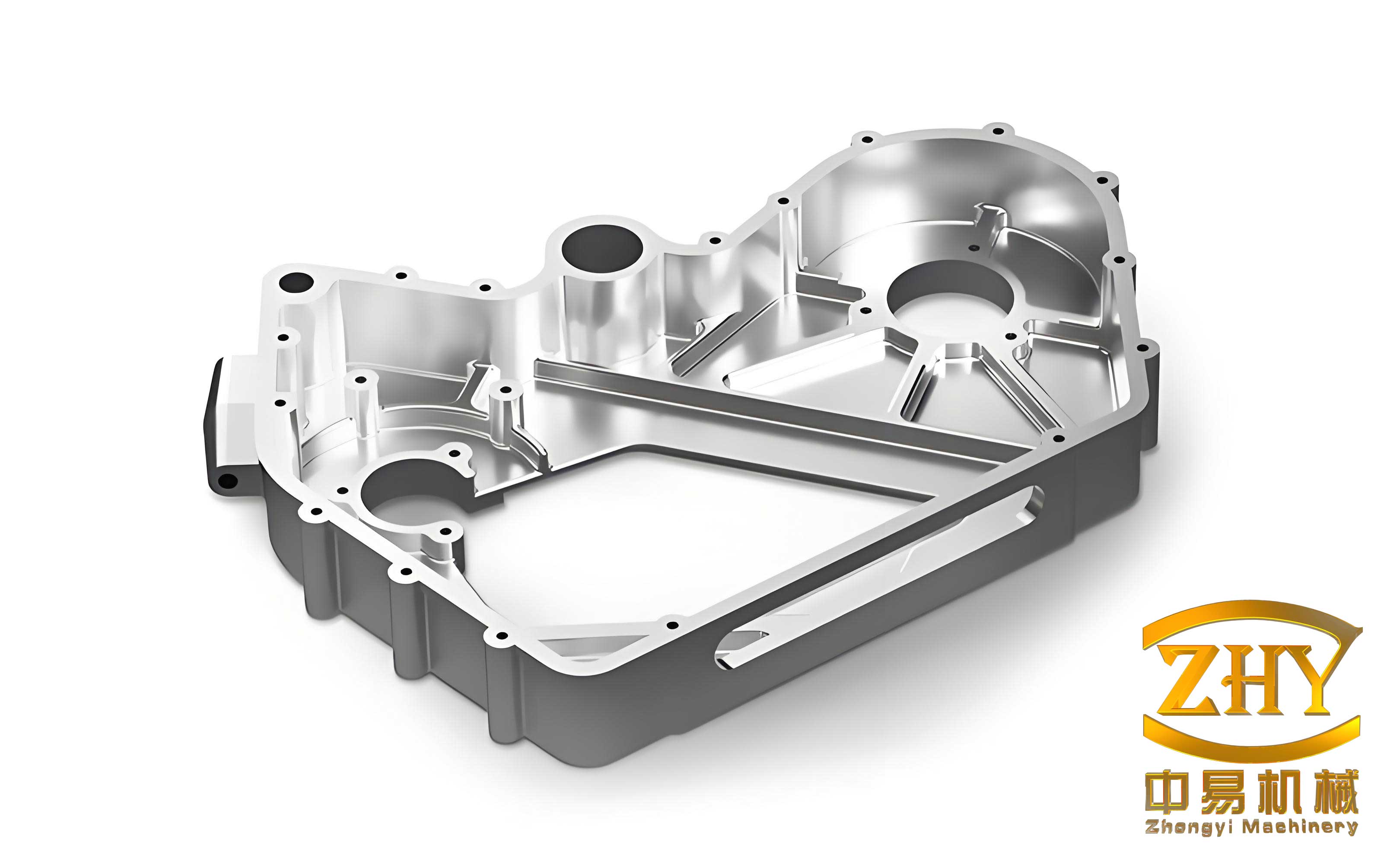
The first and perhaps most decisive engineering battle is fought during the wax pattern assembly and gating system design. For a thin-walled shell casting, the primary objectives are: directional solidification towards the feeder, minimization of turbulence during mold filling, and providing adequate rigidity to the shell during processing. Let’s evaluate four distinct approaches I have employed and analyzed.
Option 1: Vertical Mounting on a Quadralateral Runner. Here, the casting’s large face is oriented vertically. This offers excellent shell coating characteristics for recessed areas and favorable metallostatic pressure for feeding. However, the ingates must connect to non-machined surfaces, leaving unsightly scars that are unacceptable for visible components. The formula for the effective feeding distance \( L_f \) from a riser in a steel casting can be approximated, but it’s compromised if the ingate connection point acts as a chill.
Option 2: Top-Gated Inverted Assembly. This places the open face downward, fed from the top. It promotes rapid filling of thin sections but creates severe turbulence and oxide formation. The velocity of the metal stream \( v \) from a height \( h \) is given by Torricelli’s law: \( v = \sqrt{2gh} \), which can lead to splashing and entrainment in a top-gate. Furthermore, the small wax connections for such an assembly are notoriously fragile during shell building.
Option 3: Tilted Mounting on a Vertical Runner. This creative solution aims to improve coating in deep pockets. By tilting the pattern, all deep corners become more accessible. However, it creates an asymmetrical thermal profile. Feeding paths to the diagonally opposite thick sections become long and indirect, governed by a modified Chvorinov analysis across a non-uniform thermal gradient. Empirical results consistently showed shrinkage in the unfed corners. Additionally, the uneven constraint during shell firing and metal contraction often led to intolerable warpage of the large flat face.
Option 4: Optimized Vertical Mounting with Extended Feeder Links. This is the synthesis that yields success. We return to a vertical orientation for thermal symmetry but critically modify the connection. The pattern is mounted with its recess facing the central runner, and extended wax feeders (20-25mm long) link the thick sections of the casting to the main runner. This small but vital gap achieves multiple goals: it allows proper sand stuccoing around the ingate area, provides a “sacrificial” length for clean cut-off without damaging the casting, and, most importantly, acts as a thermal buffer. The extended feeder solidifies last, effectively becoming a mini-riser for the thick section of the shell casting. To maximize mold space utilization and improve shell drying, patterns are assembled in a staggered configuration. The key parameters for this gating system can be summarized as:
| Parameter | Design Consideration | Typical Value/Ratio |
|---|---|---|
| Ingate Cross-Section | Must freeze after casting section; calculated based on modulus. | Modulus \( M_{ingate} \geq 1.2 \times M_{casting\_thick\_section} \) |
| Ingate Length (Extension) | Thermal buffer, cut-off clearance, stucco access. | 20 – 25 mm |
| Pattern Spacing | Adequate for slurry drainage and sand impact. | ≥ 15 mm |
| Runner Diameter | Minimize heat loss, ensure adequate metal feed. | √(Total Casting Weight) × Process Factor |
With a robust gating strategy defined, the focus shifts to the heart of the investment casting process: building the ceramic shell. For large, thin-walled shell castings, shell integrity and dimensional stability are paramount. We employ a hybrid silicate-bonded system for its excellent de-waxing properties and cost-effectiveness, though the principles apply to advanced binder systems. The process is a careful balance of physics and chemistry.
1. Slurry Rheology and Application: The face coat slurry is the foundation. Its viscosity \( \eta \) must be low enough to penetrate fine details but high enough to build a sufficient layer. We control the binder (sodium silicate) modulus (M=3.1-3.2) and density (ρ=1.27-1.29 g/cm³). The powder-to-binder (P:B) ratio is critical: \( P:B = 1 : 1.6 \pm 0.1 \). The resulting viscosity, measured in a flow cup, is tightly controlled at 50-55 seconds. The coating thickness \( \delta_c \) per dip can be estimated for a Newtonian fluid draining under gravity:
$$ \delta_c \approx k’ \sqrt{\frac{\eta t_d}{\rho g}} $$
where \( t_d \) is the drainage time, \( \rho \) is slurry density, and \( k’ \) is an empirical constant. For corners and deep pockets, manual brushing is non-negotiable to eliminate air entrapment—a prime initiator of shell spalls or “veining” defects on the final casting. After dipping, the cluster is continuously rotated to prevent slurry pooling on flat surfaces, which creates a weak, laminated shell structure.
2. Stuccoing and Drying Dynamics: Immediate stuccoing with a fine-grained zircon sand (AFS 70-100) provides a mechanical key. The drying of the silicate binder is a diffusion-limited process. The rate of water loss \( \frac{dm}{dt} \) is governed by the humidity gradient. We enforce a controlled environment (20-24°C, 40-50% RH) with ample airflow for a minimum of 8-12 hours before the first coat is hardened.
3. Chemical Hardening Kinetics: This is where the shell gains its green strength. The reaction between sodium silicate (Na₂O·nSiO₂) and ammonium chloride (NH₄Cl) precipitates silica gel:
$$ \text{Na₂O·nSiO₂ + 2NH₄Cl -> 2NaCl + 2NH₃↑ + nSiO₂·H₂O (gel)} $$
The reaction rate is sensitive to concentration and temperature. We maintain the NH₄Cl bath at >25% concentration. The hardening time \( t_h \) must be sufficient for complete reaction through the coat thickness \( \delta_c \), following a diffusion-law relationship: \( t_h \propto (\delta_c)^2 / D \), where \( D \) is the effective diffusivity of NH₄⁺ ions. For a 0.35mm face coat, 25-30 minutes is standard. In winter, bath heating to 25-30°C is essential to maintain kinetics.
4. The Delicate De-waxing Phase: De-waxing is a thermal shock event. The shell is plunged into a near-boiling aqueous solution (≥95°C) containing ~5% NH₄Cl. The rapid heat transfer melts the wax, which expands. The internal pressure \( P \) generated must be less than the hot wet strength of the shell. The Clausius-Clapeyron relation gives insight, but practically, we control it by ensuring the shell is absolutely dry before de-waxing and by limiting immersion time to just enough for complete wax removal (typically 12-15 minutes). Prolonged exposure to sub-boiling water causes wax expansion and shell cracking.
| Process Stage | Key Control Parameter | Target Value / Formula | Rationale |
|---|---|---|---|
| Face Coat Slurry | Viscosity & P:B Ratio | η = 50-55 s (Flow Cup); P:B = 1:1.6 | Ensures detail replication & adequate coat thickness. |
| Drying (Pre-Hardening) | Time & Environment | t ≥ 8h @ 40-50% RH, 22°C | Allows controlled water migration; prevents cracks. |
| Chemical Hardening | Bath Concentration & Time | [NH₄Cl] ≥ 25%; t_h ≈ 30 min for face coat | Guarantees complete gelling reaction through coat thickness. |
| De-waxing | Medium Temperature & Time | T ≥ 95°C; t ≤ 15 min | Maximizes wax melt rate, minimizes shell exposure to pressure. |
The fired ceramic mold must transform from a hydrated gel into a strong, porous refractory. For shell castings with large faces, firing is a critical stress-relief step. The shells are placed in the furnace with careful spacing to ensure uniform heat exposure and prevent mechanical load. The firing curve is designed to: a) remove residual chemically bound water slowly to avoid steam pressure explosions, and b) achieve sintering for maximum strength. A typical profile is: ramp to 300°C at 100°C/hr, hold for 60 minutes; then ramp to 850-880°C at 150°C/hr, hold for 90-150 minutes. The high-temperature soak ensures the mold is fully transformed and thermally equilibrated. The modulus of rupture (MOR) of the shell increases with firing temperature up to a point, following an Arrhenius-type relationship for sintering. The fired shell must be poured while its temperature is above 600°C to prevent premature chilling of the thin sections of the steel casting.
For carbon steel shell castings like ZG230-450, melting and pouring practices are tailored to fill thin sections and minimize inclusions. The melt is thoroughly deoxidized using a combination of aluminum and silicon in the ladle to prevent pinhole porosity. The pouring temperature is a critical compromise. Too low, and cold shuts form in the 4mm walls; too high, and metal-mold reaction increases. We target a superheat \( \Delta T \) above the liquidus (approx. 1510°C for this steel):
$$ \Delta T = T_{pour} – T_{liquidus} $$
The target \( \Delta T \) is 30-50°C, resulting in a pouring range of 1540-1560°C. The fluidity length \( L_f \) of the steel is proportional to superheat and inversely proportional to the square root of the section thickness \( d \) for a given mold material: \( L_f \propto \frac{\Delta T}{\sqrt{d}} \). This quantifies why adequate superheat is non-negotiable for thin-wall shell castings. The mold is poured swiftly under a protective slag cover to prevent oxide entrainment.
The post-casting processes must respect the fragility of the now-solid but still hot and delicate thin-walled structure. The shell is mechanically vibrated off, but the intensity and duration are controlled to prevent bending or cracking the slender walls. The gate removal is performed using high-speed abrasive cut-off wheels, taking advantage of the extended feeder length to avoid heat-affected zones on the casting itself. Shot blasting is done with fine steel media (0.4-0.6mm diameter) at a lower pressure for a shorter duration (15-20 minutes) compared to bulkier castings. This cleans the surface without peening over fine details or distorting the geometry. Finally, the castings undergo a full annealing heat treatment (heating to ~900°C, slow cooling) to relieve all residual stresses from solidification and cooling, ensuring dimensional stability for final machining. This step is crucial for preventing distortion during subsequent machining of the large planar faces.
In conclusion, the reliable production of high-integrity, thin-walled shell castings is a testament to systems engineering in the foundry. It demands an integrated view where pattern assembly, gating design, colloidal chemistry of shell building, thermal management during firing and pouring, and gentle post-processing are all optimized in concert. There is no single “correct” answer, but a series of informed compromises guided by fundamental principles of fluid flow, heat transfer, and solid mechanics. The extended feeder in the vertical mounting scheme, the meticulously controlled slurry rheology and hardening kinetics, and the tailored thermal cycles all serve one goal: to balance the conflicting demands of feeding thick sections without distorting thin ones, of creating a strong mold that can also be removed, and of filling intricate detail without introducing turbulence-born defects. By respecting these principles and maintaining rigorous control at every stage, first-pass quality yields exceeding 75% for such demanding components are not only possible but expected. This holistic, first-principles approach is what defines the art and science of producing premium shell castings.