
In my experience with advanced foundry processes, lost foam casting has emerged as a revolutionary technique, often hailed as the “green engineering of casting” for the 21st century. Its advantages—high dimensional accuracy, low surface roughness, minimal machining allowances, reduced environmental impact, and cost-effectiveness—make it a near-net-shape manufacturing method with immense potential. Over the years, I have witnessed its expanding application in producing truck castings, where it competes vigorously with traditional sand casting for components like differential housings, gear shells, brackets, and engine blocks. However, when my team and I implemented lost foam casting for a thin-shell cylindrical gear housing, we encountered significant distortion issues that threatened production viability. This article details our first-person journey in diagnosing and solving these problems through systematic process improvements, emphasizing how lost foam casting can be optimized for delicate geometries.
The cylindrical gear housing in question was made of QT450-10 ductile iron, with overall dimensions of 495 mm × 237 mm × 181 mm and a nominal wall thickness of 7 mm. It lacked reinforcing ribs, making it inherently prone to deformation. Under previous wet sand casting methods, the part required six cores, multiple chills, and insulating risers to address shrinkage and gas porosity, complicating production and raising costs. Switching to lost foam casting simplified the process but introduced a new challenge: warping of the large flange face, with distortions up to 5.4 mm observed. Since the machining allowance was only 2.5 mm and this face served as the primary locating surface, distortions exceeding 2.0 mm led to high rejection rates, initially over 30%. This prompted a comprehensive investigation into every stage of the lost foam casting process to identify and mitigate distortion sources.
The lost foam casting workflow involves several sequential steps: bead pre-expansion and aging, pattern molding and drying, assembly, coating application and drying, molding and compaction, pouring under vacuum, and shakeout. Distortion can propagate through stages 2 to 8, but it often originates in early phases like mold design and pattern handling. Our approach was to enhance the polystyrene pattern’s stiffness and minimize external forces during processing. Below, I elaborate on the key measures we implemented, supported by data, tables, and formulas to underscore the technical rigor behind our solutions.
| Process Stage | Issue Identified | Solution Implemented | Impact on Distortion |
|---|---|---|---|
| Mold Design | Split pattern weakened flange integrity | Adopted whole-pattern extraction with core pulls | Reduced distortion by ~25% |
| Bead Pre-expansion | Inconsistent density affected pattern strength | Optimized bead density to 23 g/L for thin walls | Improved pattern stiffness without secondary expansion |
| Pattern Drying | External fixtures caused uneven shrinkage | Corrected patterns while pliable; allowed free drying | Ensured uniform contraction |
| Pattern Assembly | Manual handling warped flange during gluing | Used a强制校正胎具 (calibration jig) and internal扇形 supports | Maintained planar stability |
| Coating Application | Insufficient coating strength led to compaction变形 | Selected high-strength, permeable coating; increased thickness on flanges | Enhanced resistance to振动 forces |
| Molding Compaction | Excessive vibration amplitude and time deformed patterns | Reduced激振力 and time; stabilized sandbox rigidity | Minimized振动-induced warpage |
| Vacuum Pouring | Prolonged pressure holding did not affect distortion | Standardized保压 time based on trials | No significant impact found |
In lost foam casting, mold design is foundational. Initially, the pattern was split along the axis of oil passages for easy demolding, but this compromised the flange’s continuity, reducing overall stiffness. We redesigned the mold to extract the pattern as a whole, employing core pulls for through-holes. This preserved the flange’s integrity, boosting pattern rigidity perceptibly. The comparison is stark: the new design yielded patterns that felt sturdier to the touch, directly cutting distortion rates by about 25%. For thin-shell parts, I cannot overstate the importance of holistic pattern extraction in lost foam casting—it is the first line of defense against deformation.
Bead pre-expansion and aging critically influence pattern density and strength. We tested polystyrene beads at densities of 20 g/L, 23 g/L, and 26 g/L. Higher densities generally increase pattern stiffness, but at 26 g/L, we observed uncontrolled expansion during drying, exacerbating distortion. Through trial and error, we settled on 23 g/L for this thin-wall gear housing, balancing strength and stability. The relationship between bead density and pattern performance in lost foam casting is nonlinear; it requires tailoring to part geometry. Thicker sections may tolerate lower densities, but thin shells benefit from moderately elevated densities to resist handling stresses.
Pattern drying is another delicate phase. Freshly molded patterns are susceptible to warping if improperly supported. We initially used fixtures to hold the flange flat during drying, but this created temperature gradients and uneven shrinkage. Instead, we corrected distortions manually while the pattern was still pliable after demolding, then allowed it to dry freely without external constraints. This ensured homogeneous temperature distribution and consistent shrinkage, a simple yet effective tweak in our lost foam casting protocol.
For pattern assembly, we devised a calibration jig that locates on the flange’s backside bosses, clamping the face with a环形压板 to enforce flatness during gluing. Additionally, we implemented an internal扇形 support structure made of glued wooden strips, which bracing the pattern from within. This replaced traditional crisscross external supports, reducing labor and improving accuracy. The jig and internal bracing became indispensable tools in our lost foam casting line for thin-shell parts, virtually eliminating assembly-induced warps.
Coating application in lost foam casting serves dual purposes: providing a barrier for metal-pattern replacement and reinforcing the pattern. We evaluated numerous coatings, prioritizing常温 strength and permeability. The selected coating offered a balance, applied in two overall layers (0.8–1.5 mm thick) with an extra layer on the flange (2.0–2.5 mm thick). The coating’s strength counteracts compaction forces, while its permeability prevents gas-related defects. We also trained operators in gentle dipping techniques to avoid mechanical distortion. Furthermore, custom drying racks ensured patterns dried without sagging, a minor but crucial adjustment in our lost foam casting process.
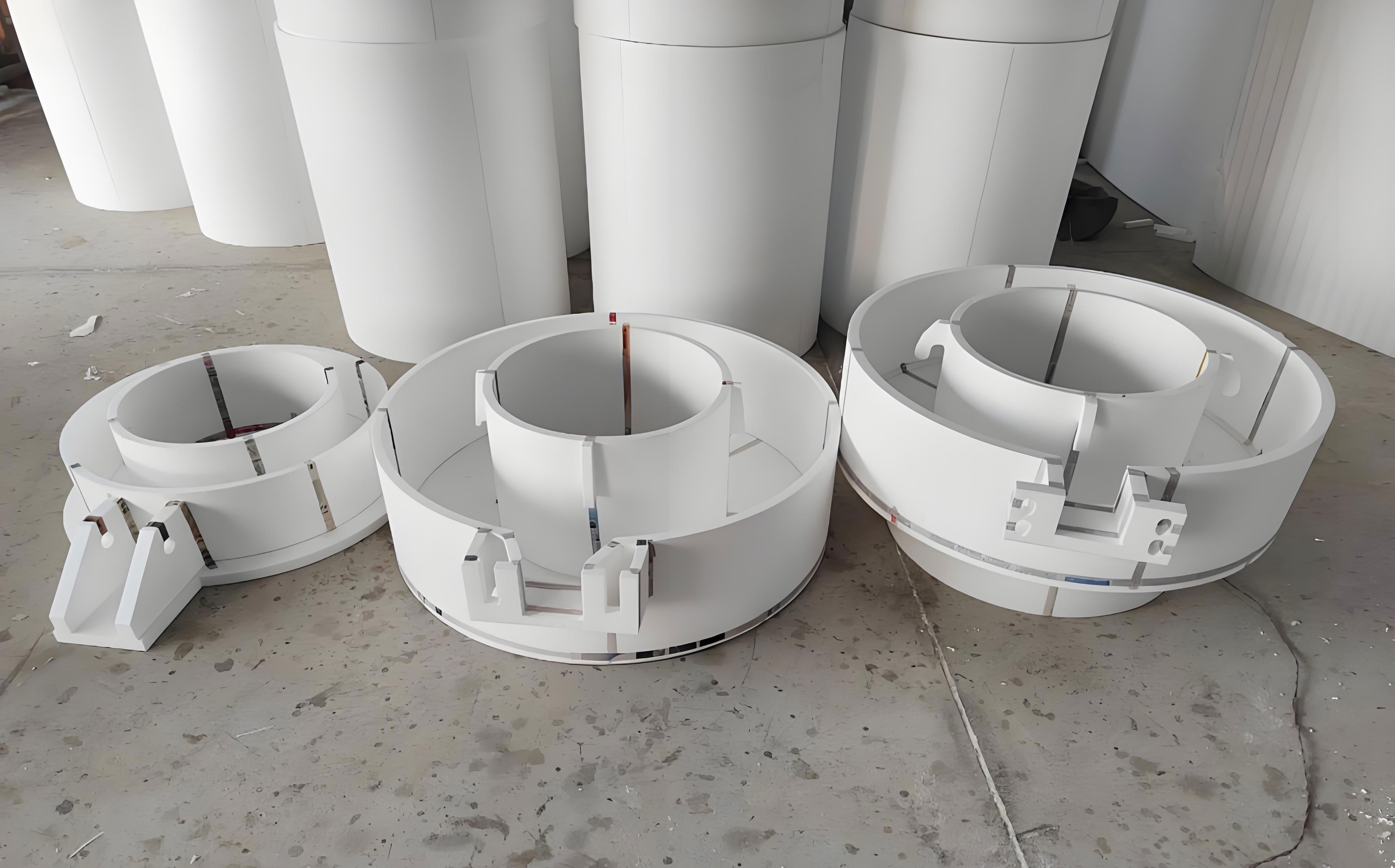
Molding and compaction represent the core of lost foam casting, where vibration parameters dictate sand filling and pattern stability. Our vibratory table, a SYZ-04悬浮式 model, uses air springs and激振 motors for three-dimensional compaction. The vibration acceleration and amplitude are key variables. The relationship is given by:
$$a = \frac{(2\pi f)^2 A}{g}$$
where \(a\) is the vibration acceleration in \(g\), \(f\) is the frequency in Hz, \(A\) is the amplitude in mm, and \(g\) is gravitational acceleration. In lost foam casting, high-frequency, low-amplitude vibrations are preferred to fluidize sand without damaging patterns. Initially, we measured inconsistent accelerations across sandboxes (0.4–2.0 \(g\)), attributed to sandbox deformation up to 5 mm. By reinforcing sandboxes and optimizing parameters, we reduced the vibration time from 55 s to 33 s and the eccentricity from 110 mm to 90 mm. The revised settings, detailed below, minimized pattern distortion during compaction:
| Parameter | Initial Value | Optimized Value | Rationale |
|---|---|---|---|
| Frequency (\(f\)) | 38–60 Hz | 40–50 Hz | Reduced共振 risk |
| Amplitude (\(A\)) | 0.3–0.6 mm | 0.3–0.4 mm | Lower displacement |
| Vibration Time | 55 s | 33 s | Shorter exposure |
| Acceleration (\(a\)) | Up to 2.0 \(g\) | ~1.0–1.5 \(g\) | Controlled force |
We also explored the effect of vacuum holding time after pouring, testing 0 s, 60 s, 120 s, 180 s, and 300 s. No correlation was found between holding time and distortion, indicating that solidification stresses in this thin-shell design were not significantly influenced by post-pouring pressure. Thus, we standardized a holding time sufficient for complete metal solidification without exacerbating warpage.
The cumulative impact of these interventions was profound. Distortion scrap rates plummeted from over 30% to below 0.5%, and overall rejection fell under 5%. This success underscores the sensitivity of lost foam casting to process nuances, especially for thin-walled components. Each measure contributed incrementally, but the synergy of stiff patterns, careful handling, robust coatings, and gentle compaction was transformative. Lost foam casting, when finely tuned, can deliver exceptional precision even for challenging geometries.
Reflecting on this project, I recognize that lost foam casting is not a one-size-fits-all solution; it demands meticulous adaptation to part-specific constraints. The公式 and tables we developed now guide our production of similar thin-shell castings. Future work may involve computational modeling to predict distortion hotspots or advanced materials for patterns and coatings. Nevertheless, the principles remain: prioritize pattern integrity, control densities, minimize external forces, and optimize vibration dynamics. Lost foam casting continues to evolve, and our experience adds to the growing body of knowledge that makes it a cornerstone of modern foundry practice.
In conclusion, the journey from high distortion to near-zero rejects for the cylindrical gear housing was a testament to systematic problem-solving in lost foam casting. By addressing each process stage with data-driven adjustments, we turned a problematic part into a reliable product. This case study highlights that success in lost foam casting hinges on holistic process control, where every parameter—from bead density to振动 frequency—plays a role in achieving dimensional stability. As lost foam casting gains traction for complex castings, such insights will be invaluable for foundries worldwide.