
The production of large, pressure-containing components like valve bodies represents a significant challenge in the foundry industry. As a foundry engineer specializing in complex castings, I have encountered numerous projects that test the limits of conventional methods. Among these, the development of a robust process for a DN500 butterfly check valve shell stands out as a comprehensive case study in overcoming geometric complexity, dimensional control, and soundness requirements. The successful casting of such large shell castings requires a meticulous, integrated approach from pattern design to final inspection.
The primary challenge with this particular valve shell was its geometry and performance specifications. The component was an arc-shaped structure with multiple intersecting planes and pronounced thermal sections, particularly at the two flanges. With a contour dimension of approximately 674mm x 350mm, a finished weight of 275kg, and an as-cast weight targeting 335kg, it was a substantial piece. The wall thickness varied significantly from 22mm to 65mm, with the largest thermal junction measuring Ø65mm. The material specification was HT200 gray iron, and the shell had to withstand a proof pressure of 1.5 MPa without any leakage, making internal soundness non-negotiable. Furthermore, as-cast surfaces, including raised lettering and logos, required clarity and finish, limiting the use of extensive machining for correction.
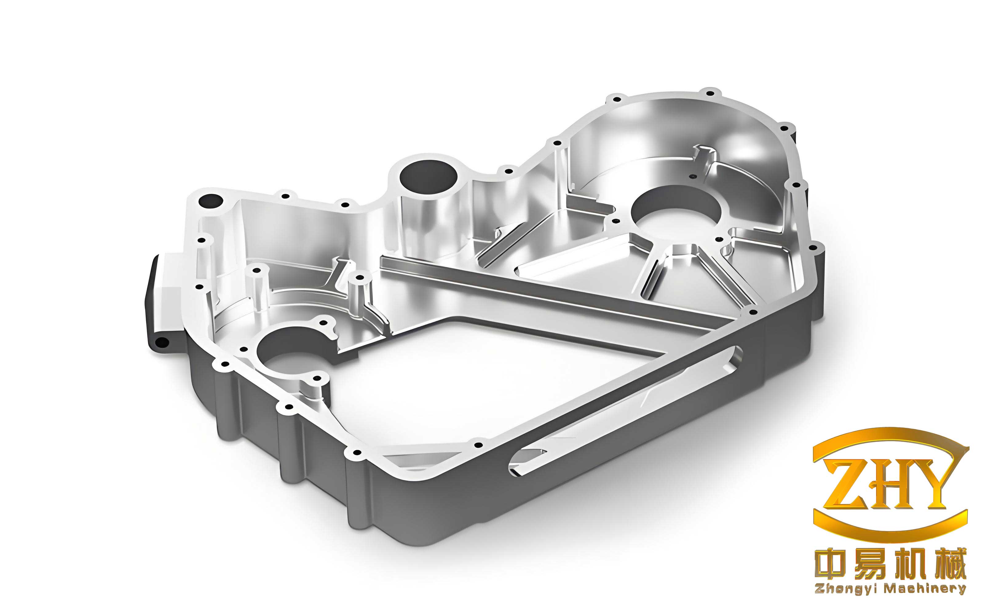
The historical data from similar, larger shells like DN600 and DN500 models indicated recurring issues: warping (distortion) of the flanges and difficulties in maintaining the precise parallel alignment and center-distance between them. These defects often stemmed from insufficient mold rigidity and uneven solidification stresses. Therefore, the core philosophy for this new shell castings process was built on three pillars: maximizing mold stability, controlling solidification through strategic feeding, and proactively compensating for predictable dimensional shifts.
Foundational Process Design and Innovation
The first critical decision was the selection of the parting line. A vertical split was chosen, positioning the upper flange in the cope and the lower flange along with the main body in the drag. This arrangement offered several advantages for producing high-quality shell castings. It avoided the risk of core lift or shift during assembly, which could directly affect the internal cavity dimensions and flange spacing. Most importantly, to combat the historical issue of mold flexure, a key innovation was implemented: the traditional loose pieces or cheek pieces (box rings) around the flanges were eliminated and replaced with precisely shaped sand cores.
This substitution of cores for box rings was transformative. It allowed the majority of the mold cavity to be situated within the sturdy drag flask, dramatically increasing the overall rigidity and strength of the mold assembly during pouring and solidification. This core-based design effectively eliminated the elastic deformation of the flask that previously led to flange warpage. Additionally, during core setting, the distance between the inner faces of the two flanges could be physically verified, providing an immediate checkpoint for dimensional accuracy before metal was poured. This approach is particularly beneficial for large, thin-walled shell castings where mold stability is paramount.
The molding medium selected was a skin-dried sand, providing a good balance of surface finish and collapsibility. For areas with intricate detail like the logo and markings, core sand with an additional binder was used to ensure sharp definition.
Rigorous Gating and Feeding System Calculation
To achieve a sound casting, the system for introducing and feeding the molten metal must be carefully engineered. The goal was a quiet, controlled fill from the bottom upward to minimize turbulence, slag entrapment, and oxidation. The gating was designed as a semi-pressurized system, known for its good slag-trapping capability and controlled fill rate.
Metal was introduced at the bottom flange area. Seven triangular-section ingates were distributed to ensure even distribution. A circular runner was placed on a core just above the lower flange. The key parameters were determined through systematic calculation:
1. Pouring Time (t): Critical for temperature gradient control in heavy shell castings.
$$ t = S \sqrt{G} $$
Where \( G = 335 \, \text{kg} \) (casting weight) and \( S = 1.63 \) (empirical coefficient for wall thickness).
$$ t = 1.63 \times \sqrt{335} \approx 30 \, \text{seconds} $$
2. Total Ingate Area (\( \Sigma F_{ingate} \)): Determines the fill speed.
$$ \Sigma F_{ingate} = \frac{G}{0.31 \mu \sqrt{H_p}} $$
Where \( \mu = 0.48 \) (total flow resistance coefficient) and \( H_p = 42 \, \text{cm} \) (mean effective metal head).
$$ \Sigma F_{ingate} = \frac{335}{0.31 \times 0.48 \times \sqrt{42}} \approx 12.6 \, \text{cm}^2 $$
This calculated value was cross-verified against standard charts for gray iron, confirming its validity. The semi-pressurized system was then proportioned as:
$$ \Sigma F_{ingate} : \Sigma F_{runner} : F_{sprue} = 1 : 1.5 : 1.2 $$
Thus:
$$ \Sigma F_{runner} = 1.5 \times 12.6 = 18.9 \, \text{cm}^2 $$
$$ F_{sprue} = 1.2 \times 12.6 = 15.1 \, \text{cm}^2 \quad \text{(corresponding to a sprue diameter of ~44mm)} $$
3. Feeding System (Risers): The thermal centers at the flanges and upper body sections required dedicated feeders. A simplified yet effective method based on the thermal junction diameter (\(d_y = 65mm\)) was used for these shell castings:
– Riser Neck Diameter: \( d = 0.85 \times d_y = 55mm \)
– Riser Diameter: \( D = 1.4 \times d_y = 91mm \)
– Riser Height: \( H = 2.3 \times D \approx 210mm \)
Three top risers were placed, each with an estimated weight of 10kg. The required feed metal for the casting shrinkage (assuming 0.8% for gray iron) is:
$$ 335 \, \text{kg} \times 0.008 = 2.68 \, \text{kg} $$
The feeding capacity of three risers at a typical 20% efficiency is:
$$ 3 \times (10 \, \text{kg} \times 0.20) = 6.0 \, \text{kg} $$
This provided a comfortable safety margin, ensuring adequate feeding to prevent shrinkage porosity.
| Parameter | Symbol | Value | Unit |
|---|---|---|---|
| Pouring Time | t | 30 | seconds |
| Total Ingate Area | ΣF_ingate | 12.6 | cm² |
| Runner Area | ΣF_runner | 18.9 | cm² |
| Sprue Area | F_sprue | 15.1 | cm² |
| Thermal Junction Dia. | d_y | 65 | mm |
| Number of Risers | – | 3 | – |
| Total Riser Feed Capacity | – | 6.0 | kg |
Strategic Use of Allowances and Process Parameters
Inconsistent section thickness inherently leads to uneven solidification and contraction stresses. For these shell castings, the thin center section would solidify first, restraining the contraction of the more massive, slower-cooling flanges. To compensate for the resulting dimensional deviations and ensure the final machined dimensions, specific allowances were incorporated into the pattern equipment.
A uniform shrinkage allowance of 0.8% was applied. However, additional engineering allowances were crucial:
– Margin (Padding) on Flange Interiors: Each interior face of the two flanges received an extra 1.6mm. This directly counteracts the inward pulling effect caused by the restraint from the center body.
– Core Print Negative Allowance: The large sand core that replaced the box ring was given a “negative” or reduction of 0.5mm at its parting to ensure proper closure and accurate core positioning.
– Wall Thickness Allowance: An additional 2mm was added to the nominal wall thickness of the cylindrical body section. This serves as a safety factor for pressure integrity, accounting for any micro-shrinkage or minor shifts, guaranteeing the minimum required wall after any cleaning or finishing.
| Feature | Type of Allowance | Value (mm) | Purpose |
|---|---|---|---|
| Overall Casting | Linear Shrinkage | 0.8% | Compensate for solidification contraction |
| Flange Interior Faces | Margin / Padding | +1.6 | Counteract restraint-induced distortion |
| Main Body Core | Parting Negative | -0.5 | Ensure core fit and alignment |
| Cylindrical Body Wall | Safety Thickness | +2.0 | Guarantee minimum pressure wall thickness |
Defect Prevention and Quality Assurance Strategy
The integrated process design was inherently geared toward preventing the common defects in large shell castings. A summary of the targeted defects and the corresponding countermeasures is outlined below:
| Potential Defect | Root Cause | Preventive Measure in This Process |
|---|---|---|
| Flange Warping/Distortion | Mold flexure, uneven cooling stress | Use of rigid sand cores代替 box rings; majority of mold in strong drag. |
| Incorrect Flange Spacing | Core shift, mold wall movement | Vertical parting; core design allows for positive spacing check during assembly. |
| Shrinkage Porosity (at thermal centers) | Insufficient feed metal | Three top risers sized via thermal junction method, with >100% required feed capacity. |
| Slag Inclusions, Cold Shuts | Turbulent filling, low metal temperature | Semi-pressurized gating with bottom fill; multiple ingates for rapid, controlled filling. |
| Poor Surface Finish/Detail | Inadequate sand properties | Use of skin-dried sand for general surfaces; special core sand for logos and lettering. |
The final validation of the process came from the production results. The castings exhibited excellent surface finish, free from shrinkage cavities, slag inclusions, or cold laps. The dimensional inspection confirmed the effectiveness of the allowances: flange thickness varied only +1 to +2 mm from nominal, and the critical distance between the flanges was controlled within a tolerance of -2 to -3 mm, achieving a casting tolerance grade equivalent to CT12. Most importantly, all pressure test specimens held at 1.5 MPa without any trace of leakage, confirming the internal soundness of the shell castings.
Conclusion and Broader Implications
The successful development of the DN500 valve shell casting process underscores a holistic engineering methodology. It demonstrates that challenging large shell castings can be reliably produced by synergistically combining core design innovation, calculated gating and feeding, and proactive dimensional compensation. The replacement of traditional box rings with integrated sand cores proved to be a pivotal solution for enhancing mold rigidity, a principle applicable to many other large, box-like or flange-heavy castings. The systematic approach to calculating feeding requirements, coupled with strategic allowances, ensures both geometric accuracy and metallurgical soundness. This case serves as a valuable reference framework for foundry engineers facing similar challenges in producing high-integrity, complex geometry castings for critical pressure applications.