
In my extensive experience within the foundry industry, producing critical components like bearing housings for energy and drainage systems presents significant technical hurdles. One of the most challenging projects I have encountered involved a high-strength, thick-section grey iron casting for a large bearing housing. This specific grey iron casting, with a material specification of HT300 and a weight of approximately 4000 kg, is a quintessential example of a heavy-walled grey iron component where differential wall thickness poses a severe risk of shrinkage defects. The primary challenge was to eliminate concentrated shrinkage porosity and cracks in the ultra-thick sections, specifically a base face with a wall thickness of 250 mm, while other sections varied from 30 mm to 80 mm. The permissible defect level was zero for porosity, cracks, sand inclusions, and shrinkage. This article details my first-person journey in analyzing the problem and implementing a successful工艺改进 through systematic redesign, simulation, and process parameter optimization,全部 focused on enhancing the quality of this complex grey iron casting.
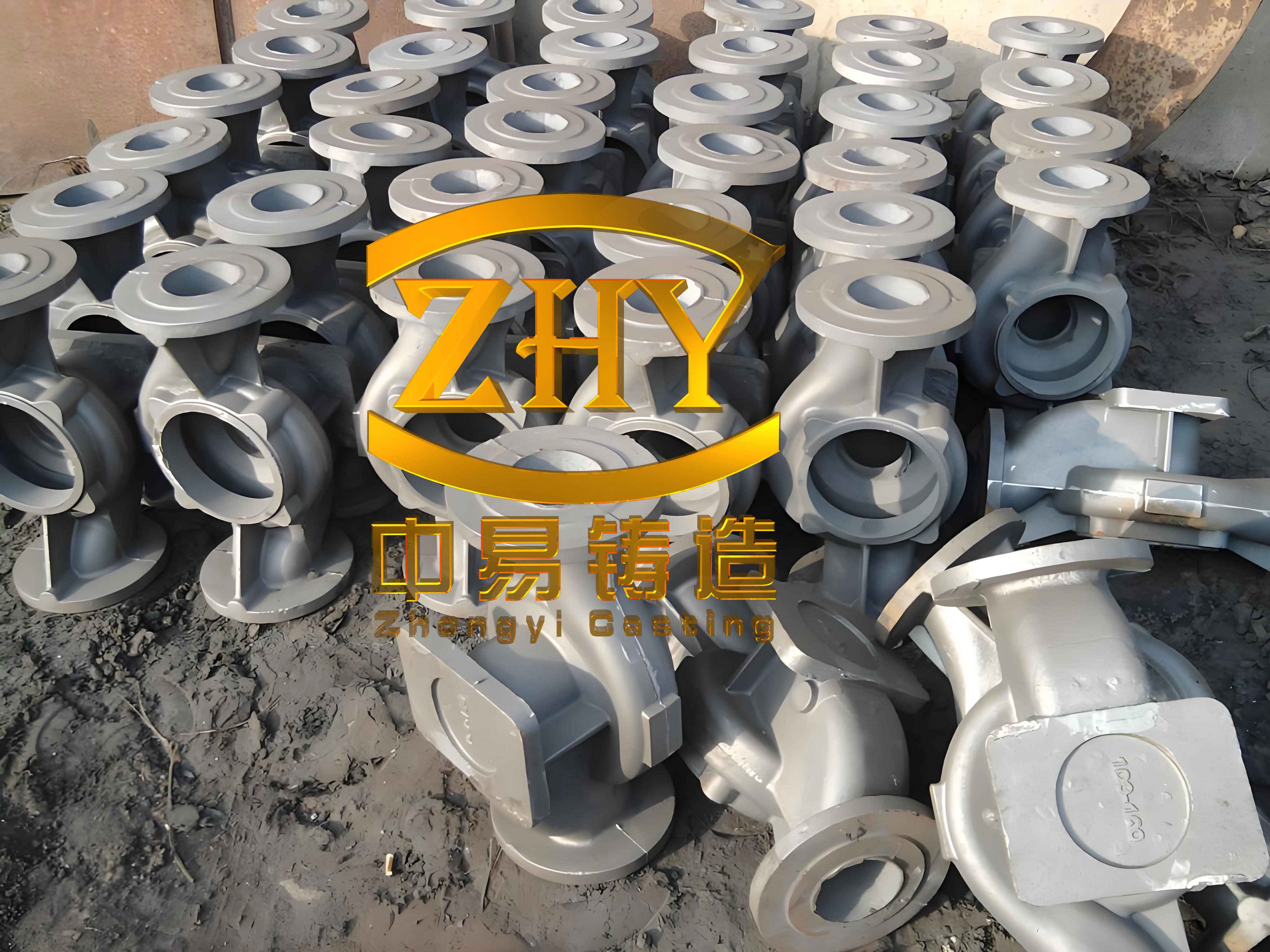
The structural characteristics of this bearing housing grey iron casting were the root cause of the manufacturing difficulties. The extreme disparity in wall thickness created inherent thermal gradients during solidification. The base section, acting as a massive thermal mass, would remain liquid long after the thinner walls solidified. This disrupted sequential solidification and created isolated liquid pools prone to shrinkage. The key functional surfaces were the internal bore and the bearing seat faces, with the thick base face also being a critical machined area. In grey iron casting, such thick sections are notorious for promoting coarse graphite formation and reducing mechanical properties due to slow cooling. The table below summarizes the critical wall thickness dimensions that defined this challenging grey iron casting.
| Feature | Wall Thickness (mm) | Description |
|---|---|---|
| Base Face | 250 | Maximum thickness, primary location for shrinkage |
| Main Cylindrical Body | 80 | Predominant wall thickness |
| Minimum Section (certain radii) | 30 | Thinnest part of the structure |
My initial process for this grey iron casting employed a conventional approach using resin sand manual molding. To ensure the quality of the critical machined surfaces (internal bore and seat faces), the original casting orientation placed the entire casting in the drag (lower mold half), with the thick base face facing downward. The parting line was at the top of this thick section. A pressurized gating system was used with a ratio of Sprue : Runner : Ingate = 1 : 1.8 : 0.85, with iron entering from the side at two levels. Chills were placed against the thick base face, and several top-feeding risers, shaped as duck-bill risers, were positioned on the top surface (which was the thinner section). The melting composition and pouring temperature were controlled as per standard practices for HT300 grey iron casting. The initial chemical composition and key process parameters are tabulated below.
| Parameter | Value or Specification |
|---|---|
| Material Grade | HT300 (Grey Iron) |
| Carbon Equivalent (CE) | 3.66% |
| Chemical Composition (wt.%) | C: 3.1, Si: 1.68, Mn: 0.86, P: 0.028, S: 0.007, Cu: 0.45 |
| Pouring Temperature | 1320 – 1340 °C |
| Gating System Ratio (F_sprue : F_runner : F_ingate) | 1 : 1.8 : 0.85 (Pressurized) |
| Riser Type | Duck-bill risers on top surface |
| Auxiliary Cooling | Chills on the thick base face |
This initial grey iron casting process yielded unsatisfactory results. Out of six castings produced, four were scrapped due to severe shrinkage cavities and associated hot tears located at the roots of the top risers and in their immediate vicinity. This was a critical failure mode for this high-integrity grey iron casting. My analysis pinpointed two fundamental flaws in the original design. First, by placing the thickest section (250 mm base) at the bottom of the mold, the feeding distance from the top risers became excessively long. By the time the thick section needed liquid feed metal during the final stages of solidification, the feeding channels (riser necks) had already frozen shut. Second, the sprue was positioned too close to the casting body, creating a severe hot spot that delayed local solidification and exacerbated the shrinkage problem. The basic solidification dynamics can be described by Chvorinov’s rule, which states that the solidification time \( t_f \) is proportional to the square of the volume-to-surface area ratio (modulus \( M \)):
$$ t_f = C \cdot M^2 = C \cdot \left( \frac{V}{A} \right)^2 $$
Where \( V \) is the volume of the section, \( A \) is its surface area, and \( C \) is a mold constant. For the thick base with a very high modulus \( M_{base} \), \( t_f \) was significantly longer than for the thinner sections. The original riser placement failed to maintain a thermal gradient conducive to feeding this last-freezing hot spot. Furthermore, the feeding requirement \( V_{feed} \) for the grey iron casting can be approximated by the liquid shrinkage and the graphitic expansion, but in high-strength grey irons with lower carbon equivalents, the expansion may not fully compensate for shrinkage. The required riser volume \( V_{riser} \) must satisfy:
$$ V_{riser} \geq \frac{V_{casting} \cdot (\alpha_{liquid} + \alpha_{liquid-solid} – \eta_{graphite})}{\epsilon_{riser}} $$
where \( \alpha_{liquid} \) is the liquid contraction coefficient, \( \alpha_{liquid-solid} \) is the liquid-to-solid contraction, \( \eta_{graphite} \) is the expansion due to graphite precipitation (which is significant in grey iron casting but less so in high-strength grades), and \( \epsilon_{riser} \) is the riser efficiency. In the original setup, the riser efficiency was poor due to unfavorable thermal geometry.
To resolve these issues in the grey iron casting, I led a comprehensive工艺改进 initiative. The core philosophy was to re-establish a strong directional solidification pattern towards the risers. The first and most crucial change was to flip the casting orientation 180 degrees. The new工艺 placed the thick 250 mm base face at the top (in the cope), making it the last section to solidify and directly accessible for feeding. The critical bearing seat faces were now on the side. This simple change drastically shortened the feeding distance for the problematic heavy section. The parting line remained unchanged. The gating system was redesigned to move the sprue farther away (over 200 mm) from the casting body to reduce its thermal impact. The gating ratio was adjusted to 1 : 1.5 : 0.85, maintaining a pressurized system but with iron now entering from the side of the bearing seat. To accelerate the cooling of the massive top surface and refine its microstructure, substantial direct chills over 120 mm thick were placed on it. The riser strategy was completely overhauled. The large duck-bill risers placed directly over the thick section’s thermal center were removed, as they created their own hot spots at the junction. Instead, I opted for a combination of smaller top risers and, more importantly, a well-designed “knife-gate” or “pressing” side riser at one end of the casting. This side riser provides feed metal without creating a large contact hot spot on the critical thick section of the grey iron casting.
Concurrently, I optimized the metallurgical parameters for this grey iron casting. To improve fluidity and leverage the graphitic expansion more effectively while maintaining mechanical properties, the carbon equivalent was increased. Copper content was also raised to enhance strength without significantly increasing shrinkage tendency. The pouring temperature was strategically lowered, as the thinner sections were now at the bottom and would be filled first, reducing the risk of mistruns even at lower temperatures. This lower temperature decreases the total liquid contraction volume. The modified parameters are summarized below.
| Parameter | Optimized Value or Specification | Rationale |
|---|---|---|
| Casting Orientation | Thick base face UP (in cope) | Enables direct top feeding, promotes directional solidification. |
| Gating System | Sprue distanced >200mm, Ratio 1:1.5:0.85 | Reduces sprue hot spot, controls filling. |
| Cooling Aids | Heavy chills (>120mm) on thick top face | Accelerates cooling, refines graphite, reduces shrinkage tendency. |
| Riser Strategy | Side pressing riser + modified top risers | Avoids creating hot spots at riser contact points; provides feed metal. |
| Carbon Equivalent (CE) | 3.85% | Increases fluidity and graphitic expansion potential. |
| Chemical Composition (wt.%) | C: ~3.2, Si: ~1.9, Mn: 0.86, Cu: 0.58 | Balanced for strength and castability. |
| Pouring Temperature | 1300 – 1320 °C | Reduces total liquid contraction volume. |
To validate this new工艺 for the grey iron casting before committing to expensive tooling and production, I utilized MAGMA solidification simulation software. The initial simulation of the new design showed promise but indicated that the remaining top risers, though smaller, still posed a risk of creating shrinkage at their necks due to the persistent thermal mass. The simulation clearly visualized the isolated hot spots. The MAGMA software solves the fundamental heat transfer and fluid flow equations during casting solidification. The energy equation is central:
$$ \rho c_p \frac{\partial T}{\partial t} = \nabla \cdot (k \nabla T) + \rho L \frac{\partial f_s}{\partial t} $$
where \( \rho \) is density, \( c_p \) is specific heat, \( T \) is temperature, \( t \) is time, \( k \) is thermal conductivity, \( L \) is latent heat, and \( f_s \) is the solid fraction. The Niyama criterion, often used to predict shrinkage porosity, can be expressed as:
$$ N_y = \frac{G}{\sqrt{\dot{T}}} $$
where \( G \) is the temperature gradient and \( \dot{T} \) is the cooling rate. Areas with a Niyama value below a critical threshold are prone to microporosity. The simulation highlighted such areas near the riser contacts. Based on this, I finalized the工艺 by removing all central top risers and relying solely on the side pressing riser combined with intensified chilling. The final simulation confirmed a clean thermal gradient, with solidification progressing from the thin bottom sections towards the thick top face and finally into the side riser. The riser itself solidified after feeding was complete, confirming its efficacy for this grey iron casting.
The implementation of this optimized工艺 for the grey iron bearing housing was a resounding success. The first two trial castings were fully sound. Subsequently, a batch of 30 castings was produced with a zero scrap rate due to shrinkage. Machining of the thick base face and other critical surfaces revealed dense, defect-free metal. The mechanical properties and microstructure met all specifications for the HT300 grey iron casting. The table below presents the typical quality metrics achieved from the附铸试块 (attached test lug).
| Property | Result | Standard/Specification |
|---|---|---|
| Tensile Strength | ≥ 300 MPa | Meets HT300 requirement |
| Hardness (HB) | 180 – 200 | Within typical range for grade |
| Graphite Morphology | Type A (Flake) | Desirable form for grey iron |
| Graphite Size | Grade 4-5 (ASM) | Acceptable, no excessive coarseness |
| Pearlite Content | > 85% | Ensures high strength |
| Shrinkage Defects | None detected | Primary objective achieved |
This project on a challenging grey iron casting yielded several universally applicable conclusions for producing heavy-section grey iron components. Firstly, the casting orientation is paramount. For grey iron castings with drastic wall thickness variations, the浇注位置 must be chosen to facilitate feeding by placing the heaviest section in a position where it can be directly fed, typically at the top or near risers. This overrides the traditional rule of placing critical faces down for cleanliness; sometimes, soundness is the higher priority. Secondly, the riser design for thick-section grey iron castings requires careful consideration of the contact热节. Using riser types like pressing risers that minimize the junction modulus can prevent the riser neck itself from becoming a shrinkage site. The riser must act as a thermal attractor, not a thermal obstacle. Thirdly, chilling is an indispensable tool for grey iron casting with large masses. It not only accelerates cooling to prevent coarse graphite but also helps in shaping the solidification gradient. Fourthly, process parameters are interdependent. Lowering the pouring temperature can be viable if the filling sequence is managed correctly, and adjusting the carbon equivalent within limits can improve the innate feeding characteristics of the grey iron through controlled graphitic expansion. The combined graphitic expansion pressure \( P_{graphite} \) can be conceptually related to the rate of graphite formation \( \frac{dG}{dt} \):
$$ P_{graphite} \propto \int \beta \cdot \frac{dG}{dt} \, dt $$
where \( \beta \) is a material constant related to the specific volume change upon graphite formation. Optimizing composition to maximize this beneficial pressure in the late stages of solidification is key for grey iron casting. Finally, numerical simulation tools like MAGMA are invaluable for visualizing thermal fields, predicting shrinkage risks, and iterating designs virtually before production, saving significant time and cost, especially for complex grey iron castings. The successful resolution of this issue underscores that a holistic approach, considering geometry, thermal management, feeding design, and metallurgy, is essential for mastering the art and science of producing defect-free high-strength thick-section grey iron castings.