
In the automotive industry, safety-critical components such as bracket castings for heavy-duty truck rear axle leaf springs demand high structural integrity. These castings, typically made from spheroidal graphite cast iron, serve as vital links between the leaf spring and the vehicle frame, transmitting loads and ensuring stability. However, producing defect-free spheroidal graphite cast iron castings with complex geometries and uneven wall thicknesses presents significant challenges. Shrinkage porosity, a common defect in thick sections, can compromise mechanical properties and lead to field failures. In this article, I will detail my experience in diagnosing and resolving shrinkage issues in a spheroidal graphite cast iron bracket casting through computational simulation and process optimization, emphasizing the importance of controlled solidification.
The bracket casting in question has a mass of approximately 59 kg and overall dimensions of 637 mm × 799 mm × 389 mm. Its wall thickness varies significantly, with a general thickness of 10 mm and a maximum thickness of 47.5 mm at the frame mounting holes, creating potential hot spots. The material specification requires spheroidal graphite cast iron grade QT800-2, with key technical requirements summarized in Table 1.
| Parameter | Requirement |
|---|---|
| Material Grade | QT800-2 (Spheroidal Graphite Cast Iron) |
| Tensile Strength | ≥ 800 MPa |
| Yield Strength | ≥ 380 MPa |
| Elongation | ≥ 2% |
| Hardness | 245 – 335 HB |
| Graphite Nodularity | Grade 1-3 |
| Graphite Size | Grade 5-7 |
| Pearlite Fraction | ≥ 80% |
| Dimensional Tolerance | CT9 per ISO 8062 |
| Defect Allowance | No cracks, cold shuts, or porosity affecting performance |
The production was carried out on a high-pressure molding line using green sand molds, with a flask size of 1000 mm × 800 mm × 350/300 mm. The molding hardness, measured with an SYS-B hardness tester, was maintained between 85-95 g/mm². An automatic pouring system was employed to ensure consistency. The initial casting process utilized a horizontal parting line and cold-box cores. The gating system was designed as a partially choked system with a ratio of sprue area : runner area : ingate area = 1 : 1.8 : 1.5. Iron was introduced from both sides of the casting through seven ingates. To enhance cooling at the thick frame mounting holes, four chill plates (35 mm × 35 mm × 30 mm) were placed. Ceramic foam filters (75 mm × 75 mm × 22 mm) were installed in the runners for metal filtration. Key process parameters are listed in Table 2.
| Parameter | Value/Range |
|---|---|
| Pouring Temperature | 1390 – 1400 °C |
| Pouring Time | 20 – 22 seconds |
| Number of Castings per Mold | 1 |
| Ingate Thickness | 5 mm |
| Chill Material | Spheroidal Graphite Cast Iron (GJS-600) |
The target chemical composition for the spheroidal graphite cast iron was carefully controlled to achieve the desired microstructure and mechanical properties, as shown in Table 3.
| Element | Range |
|---|---|
| Carbon (C) | 3.60 – 3.75 |
| Silicon (Si) | 2.10 – 2.30 |
| Manganese (Mn) | 0.40 – 0.55 |
| Sulfur (S) | ≤ 0.02 |
| Phosphorus (P) | ≤ 0.05 |
| Copper (Cu) | 1.40 – 1.60 |
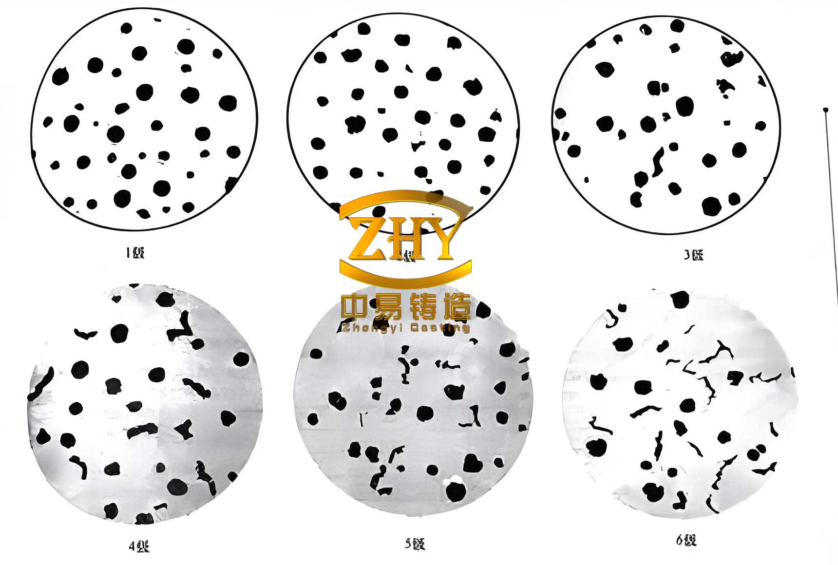
Despite adhering to these parameters, non-destructive testing via X-ray radiography revealed a significant issue: shrinkage porosity within the thick frame mounting holes. The defect rate was approximately 30% from X-ray inspection, and about 8% of machined parts showed internal shrinkage, rendering them unacceptable. This defect posed a serious risk, as porosity in these high-stress areas could lead to crack initiation and catastrophic failure under cyclic loads. The challenge was to eliminate this defect without compromising the other quality attributes of the spheroidal graphite cast iron casting.
To understand the root cause, I employed MAGMA simulation software to analyze the filling and solidification behavior of the original process. The 3D model of the casting and gating system was meshed with approximately 5 million finite difference cells, ensuring accurate thermal analysis. The material database was set to GJS-700 spheroidal graphite cast iron, with a solidus temperature of 1166 °C and a liquidus temperature of 1169 °C. The latent heat of crystallization was set to 200 kJ/kg. The mold was defined as green sand with 3.5% moisture and an initial temperature of 40 °C, while cores were modeled as cold-box silica. The interfacial heat transfer coefficients were assigned according to the software’s default settings for spheroidal graphite cast iron.
The filling simulation confirmed a smooth, non-turbulent fill with balanced metal entry from all ingates. The real insight came from the solidification simulation. The solidification sequence showed that the thin sections and the mounting hole bosses solidified first, but the thick hub of the frame mounting hole remained liquid for a prolonged period. An isolated liquid region formed in this area, indicating a lack of feeding. The Niyama criterion, a common indicator for shrinkage porosity prediction, highlighted a high probability of microporosity in the location corresponding to the actual defect.
The fundamental issue was related to the principles of solidification feeding in spheroidal graphite cast iron. The graphite expansion during eutectic solidification can compensate for some shrinkage, but in heavy sections, if the feeding path is interrupted, shrinkage porosity forms. In the original design, the thin ingates (5 mm thick) solidified rapidly, severing the feeding path from the runner system to the thick mounting hole while the hole was still in a mushy state. The chills were insufficient to overcome the thermal mass of the 47.5 mm thick section. The solidification isolation can be conceptually described by analyzing the thermal gradient (G) and the solidification rate (R). Porosity tends to form when the ratio G/√R falls below a critical value for the alloy. For spheroidal graphite cast iron, this relationship is crucial.
$$ \text{Critical Condition for Porosity: } \frac{G}{\sqrt{R}} < C $$
where \( G \) is the temperature gradient (°C/mm), \( R \) is the solidification rate (mm/s), and \( C \) is a material constant specific to the spheroidal graphite cast iron grade.
In the defective region, the simulation indicated a low thermal gradient due to the large thermal mass and a relatively slow solidification rate, leading to a value below the critical threshold. The feeding distance from the ingate was effectively zero once the thin section solidified. The required feeding demand for the isolated liquid zone can be estimated by the volume shrinkage of the alloy. The volumetric shrinkage (β) for spheroidal graphite cast iron is typically between 4-6%. The unfed volume (V_porosity) in the hot spot can be approximated by:
$$ V_{\text{porosity}} \approx \beta \cdot V_{\text{hot spot}} $$
For a hot spot volume of several hundred cubic millimeters, this leads to a significant pore volume.
Based on this analysis, the solution was to ensure directional solidification towards a dedicated feeder. The revised design involved placing a cylindrical feeder riser with a diameter of 80 mm and a height of 100 mm directly on the problematic frame mounting hole. The ingate was moved from the thin flange to the feeder neck, which had dimensions of 20 mm × 20 mm. This redesign transformed the thick section from a hot spot into the last point to solidify, fed directly by the riser. The riser acts as a liquid metal reservoir, compensating for the solidification shrinkage of the spheroidal graphite cast iron. The new design principles are contrasted with the old in Table 4.
| Aspect | Original Process | Revised Process |
|---|---|---|
| Feeding Source | Runner system via thin ingates | Dedicated feeder riser |
| Ingate Location | Thin flange (5 mm section) | Feeder neck (20 mm section) |
| Solidification Sequence | Non-directional, isolated hot spot | Directional, riser solidifies last |
| Cooling Aid | Chills (limited effect) | Feeder riser (active feeding) |
| Primary Function | Metal delivery | Metal delivery and shrinkage compensation |
The new simulation, incorporating the feeder, showed a clear directional solidification pattern from the casting extremities towards the riser. The isolated liquid zone disappeared, and the Niyama criterion no longer flagged the mounting hole area. The modulus method, a classical approach for riser sizing, validates the design. The modulus (M) is defined as volume divided by cooling surface area. For effective feeding, the riser modulus must be greater than the casting modulus at the junction. For the mounting hole section:
$$ M_{\text{casting}} = \frac{V_{\text{hot spot}}}{A_{\text{hot spot}}} $$
The selected riser had a modulus \( M_{\text{riser}} \) calculated to be approximately 1.2 times \( M_{\text{casting}} \), ensuring adequate feeding capacity for the spheroidal graphite cast iron.
To verify the simulation results, a trial production of 10 castings was conducted using the modified tooling. All castings were fully machined to inspect the critical frame mounting holes. The result was definitive: no shrinkage porosity was detected in any of the trial pieces. The internal soundness confirmed the accuracy of the MAGMA simulation and the effectiveness of the riser-based feeding strategy. While the process yield decreased slightly from 60% to about 57.9% due to the additional riser metal, and post-casting riser removal added to the cleaning workload, these were acceptable trade-offs. The primary goal of eliminating the latent defect was achieved, which directly reduces the risk of in-service failure, customer complaints, and associated warranty claims for components made from spheroidal graphite cast iron.
This case study underscores several key points for producing sound heavy-section spheroidal graphite cast iron castings. First, the expansion characteristics of spheroidal graphite cast iron do not eliminate the need for careful feeding system design, especially in complex geometries with varying sections. Second, computational solidification modeling is an indispensable tool for visualizing thermal gradients and predicting defect locations before physical trials. It allows for rapid iteration and optimization. Third, the principle of directional solidification, enforced by properly sized and placed feeders, remains fundamental. The feeder must maintain a liquid channel to the solidifying hot spot until the entire region has solidified. The feeding distance (L) for a riser in a plate-like section can be estimated by:
$$ L = k \cdot \sqrt{T} $$
where \( T \) is the plate thickness and \( k \) is a constant dependent on the alloy and mold material. For spheroidal graphite cast iron in green sand molds, \( k \) is relatively low, emphasizing the need for close riser placement to thick sections.
Furthermore, the metallurgy of spheroidal graphite cast iron plays a role. The high carbon equivalent often leads to a long solidification range, which can increase feeding demands. Alloying elements like copper, used here to promote pearlite, also affect the cooling curve and shrinkage behavior. Therefore, a holistic view integrating material science, casting design, and process engineering is essential. The successful improvement of this spheroidal graphite cast iron bracket casting demonstrates that a systematic, simulation-driven approach can solve persistent quality issues, enhance reliability, and contribute to the advancement of casting practices for high-performance ductile iron components. Future work could explore further optimization of riser size using heuristic algorithms or investigate the use of exothermic riser sleeves to improve feeding efficiency for spheroidal graphite cast iron castings.