
From my extensive experience in precision foundry operations, shell molding, utilizing thermosetting resin-coated sand, stands out for its ability to produce castings with excellent dimensional accuracy and stability, rivaling investment casting in many aspects. However, the process is not immune to the formation of various casting defects. A deep understanding of their root causes is paramount for implementing effective preventive measures. This analysis delves into the most prevalent casting defects encountered in shell molding, exploring their formation mechanisms and outlining a comprehensive control strategy encompassing material science, process design, and rigorous operational discipline.
The fundamental process involves heating a metal pattern to 180-250°C and bringing it into contact with resin-coated sand. The heat cures the resin, forming a thin, rigid shell of approximately 6-12 mm in thickness. Two such shells are then assembled using adhesives or clamps to create the mold cavity. While efficient, each stage—from sand preparation and molding to pouring and solidification—presents opportunities for casting defects to arise if not meticulously controlled.
1. Sand Inclusions (Sand Eyes)
Sand inclusions are a frequent and costly category of casting defects, manifesting as irregular cavities on or within the casting, often filled with loose or sintered sand particles. These casting defects primarily originate from two sources: loose sand grains dislodged during mold handling or assembly falling into the cavity, or surface erosion of the mold wall due to the intense thermal and mechanical冲击 of the molten metal.
Primary Causes:
- Inadequate surface strength or density of the shell mold/core.
- Presence of loose sand (flash, fins, unfused sand) on the mold cavity surface prior to closing.
- Turbulent metal flow during pouring, which scours the mold wall.
- Poor gating design lacking proper flow reduction mechanisms.
Proactive Prevention Strategies:
- Material Control: Strictly specify and monitor the properties of the coated sand to ensure high hot strength and low friability. The binder system’s integrity is crucial. A simplified model for the force required to dislodge a particle involves the interfacial strength ($\tau_i$): $$F_d \propto \tau_i \cdot A_c$$ where $A_c$ is the contact area between the sand grain and the mold matrix. Maximizing $\tau_i$ through optimal resin chemistry and curing is key.
- Process Discipline: Implement rigorous mold cleaning procedures before assembly. Ensure gentle, precise mold closing to prevent disturbance. Seal all openings (pouring cup, vents) after closing to prevent foreign material ingress.
- System Design: Employ gating systems designed for laminar flow. This often involves using a choke within the system to reduce velocity and prevent direct impingement on mold walls. The use of ceramic filters is highly effective in trapping eroded particles.
| Defect Type | Primary Root Cause | Key Control Parameter | Typical Countermeasure |
|---|---|---|---|
| Sand Inclusion | Mold Erosion / Loose Sand | Mold Surface Strength, Metal Velocity | Tapered Sprue, Ceramic Filter, Mold Wash |
| Penetration/Burn-on | Metal Infiltration into Sand Pores | Sand Fineness, Pore Size, Metal Pressure | Finer Base Sand, Refractory Coating |
| Gas Porosity (Invasive) | Gas from Mold Core | Mold Gas Evolution Rate, Venting Efficiency | Low-Gas Sand, Adequate Vents, Vacuum Assist |
| Shrinkage Cavity | Inadequate Liquid Feed | Feeding Distance, Temperature Gradient | Directional Solidification, Adequate Riser |
2. Metal Penetration and Burn-on
These surface casting defects result in a rough casting surface fused with sand material. Metal penetration is a mechanical process where molten metal infiltrates the interstitial spaces between sand grains. Burn-on or chemical adhesion involves a chemical reaction between the metal oxides (e.g., FeO) and the silica sand (SiO₂) to form low-melting-point ferrous silicates that cement the sand grains to the casting.
The penetration depth ($\lambda_p$) can be approximated by considering the capillary pressure and the dynamic pressure of the metal:
$$\lambda_p = \sqrt{\frac{\gamma_{lv} \cos\theta \cdot t}{\eta}} \cdot \frac{r}{2}$$
where $\gamma_{lv}$ is the liquid-vapor surface tension, $\theta$ is the contact angle, $t$ is the contact time, $\eta$ is the metal viscosity, and $r$ is the average pore radius. This highlights that finer pore structure (smaller $r$) directly reduces penetration.
Proactive Prevention Strategies:
- Refractoriness: Use high-purity silica sand (≥98% SiO₂ for steel castings). For demanding applications, consider zircon or chromite sands.
- Mold Density: Optimize shell shooting parameters (pressure, time) to achieve a dense, uniform mold structure with minimal interconnected porosity.
- Thermal Management: Lower pouring temperatures to the minimum required for complete filling to reduce thermal attack. Increase pouring speed strategically to shorten mold-metal contact time, but avoid turbulence.
- Protective Barriers: Apply refractory coatings (zircon- or alumina-based) to the mold cavity surface. These coatings fill surface pores and present a more refractory, non-wettable barrier to the metal. The coating thickness ($d_c$) should be optimized: too thin is ineffective, too thick can cause other defects like veining. $$d_{c,opt} \approx 2 \cdot \bar{G}_s$$ where $\bar{G}_s$ is the average sand grain size.
- Design & Tooling: Ensure uniform shell thickness and heating in the tooling to prevent “green” (uncured) spots which have low strength and high gas evolution.
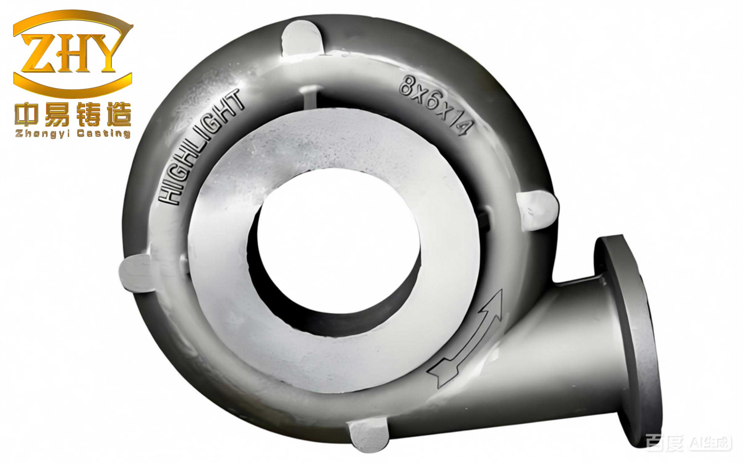
3. Porosity: Gas and Shrinkage Defects
Porosity represents a critical class of internal casting defects that severely compromise mechanical properties. It is essential to differentiate between gas porosity and shrinkage porosity, as their causes and remedies differ.
3.1 Gas Porosity appears as spherical or elongated smooth-walled cavities. Invasive gas porosity comes from mold/core gases (from binder decomposition) being forced into the solidifying metal. Subsurface pinholes often result from a reaction within the metal, such as C-O reaction in steels producing CO gas upon solidification.
The volume of gas evolved from the mold ($V_g$) is a function of temperature and binder content: $$V_g(T) = k_B \cdot m_B \cdot \exp\left(-\frac{E_a}{RT}\right)$$ where $k_B$ is a constant, $m_B$ is binder mass, $E_a$ is activation energy for decomposition, $R$ is gas constant, $T$ is temperature. Reducing $m_B$ (using low-binder sands) and providing venting paths are critical.
3.2 Shrinkage Porosity appears as irregular, dendritic, and often interconnected cavities in the last-to-freeze regions (thermal centers). It results from inadequate feeding during the liquid-to-solid phase change. The fundamental requirement to prevent shrinkage is ensuring a positive pressure gradient toward the thermal center during solidification, often achieved via risers (feeders). The famous Chvorinov’s Rule helps design feeding: $$t_s = B \cdot \left(\frac{V}{A}\right)^n$$ where $t_s$ is solidification time, $V$ is volume, $A$ is surface area, $B$ is a mold constant, and $n$ is an exponent (~2). Risers must be designed to solidify last ($(V/A)_{riser} > (V/A)_{casting}$).
Proactive Prevention Strategies:
- For Gas Porosity:
- Use low-gas-generating (< 12 ml/g) coated sands.
- Ensure thorough drying/curing of molds/cores. Pre-dry molds at 150-200°C if necessary.
- Design effective venting: use venting pins (1-2 mm diameter) in cores, create vent channels in parting lines.
- Metal Treatment: Melt under protective atmospheres, use degassing techniques, and hold at temperature to allow gas flotation.
- Control pouring: Use a tapered sprue and maintain a non-turbulent fill to avoid air entrainment.
- For Shrinkage Porosity:
- Metallurgical Control: Optimize composition (e.g., higher Carbon Equivalent in cast iron promotes graphitization expansion).
- Thermal Gradient Management: Design gating and risering for directional solidification toward the riser. Use chills (internal or external) to accelerate cooling in heavy sections and create a defined solidification front. The effectiveness of a chill is related to its chilling power ($C_p$) and contact area: $$Q_{chill} = C_p \cdot A_{chill} \cdot (T_m – T_{chill}) \cdot \sqrt{t}$$
- Process Control: Reduce pouring temperature to minimize total liquid contraction volume.
- Mold Rigidity: Use high-strength shell materials to resist mold wall movement from metallostatic pressure, which can enlarge shrinkage cavities.
4. Surface Defects: Orange Peel and Scabs
These are severe surface casting defects where the casting surface appears wrinkled or has rough, scab-like protrusions containing sand. They occur when the surface layer of the mold partially collapses or disintegrates due to excessive thermal loading and/or metal冲刷, and the resulting sand-metal slurry is incorporated into the casting surface. This is particularly common in steel castings where temperatures are higher.
Proactive Prevention Strategies:
- Maximize the hot strength and thermal shock resistance of the shell mold through optimal sand formulation and complete, uniform curing.
- Apply high-refractoriness mold washes specifically in areas prone to high heat load (e.g., near gates, heavy sections).
- Implement “soft” gating practices—use runner extensions, splash cores, or vortex gates to dissipate metal stream energy before it enters the main cavity.
- In tool design, avoid excessively thick shell sections in gating areas which can lead to under-curing (“green” strength). Consider using high-thermal-conductivity materials (e.g., copper) for heavy mold inserts to ensure thorough heat penetration and curing.
5. Cracking: Hot Tear and Cold Crack
Cracking is a disastrous category of casting defects leading to total rejection. Hot tears are intergranular fractures that occur during solidification when the coherent solid network is weak and cannot withstand thermally induced stresses (from restricted contraction). They appear as ragged, oxidized cracks often in hot spots or at section changes. Cold cracks occur after solidification, at lower temperatures, when the stress from residual stresses and/or phase transformations exceeds the material’s tensile strength. They appear as straight, clean cracks.
The susceptibility to hot tearing ($S$) is often modeled as a function of the vulnerable temperature range where the material has low strength and coherency: $$S \propto \int_{T_{coh}}^{T_{sol}} \frac{\alpha(T) \cdot \Delta T_{local}}{\sigma_u(T)} dT$$ where $\alpha$ is thermal contraction coefficient, $\Delta T_{local}$ is the local temperature gradient causing strain, and $\sigma_u$ is the ultimate tensile strength of the semi-solid material.
Proactive Prevention Strategies:
- Mold Compliance: Ensure the shell mold has sufficient collapsibility or yield after the metal solidifies to avoid creating high restraint stresses. Sand additives can promote breakdown.
- Metallurgical Control: Strictly limit elements that promote hot shortness (e.g., Sulfur, Phosphorus in steels). Modify grain structure with inoculants or refiners.
- Design Optimization: Implement generous fillet radii at junctions to reduce stress concentration. Use staggered section changes and reinforcing ribs where possible. Design uniform wall thickness.
- Thermal Management: Use chills to promote uniform cooling rates and reduce thermal gradients. Place inner gates away from isolated hot spots to balance temperature fields.
- Process Control: For sand-cushioned molds, avoid premature knockout. For shell molds, control cooling to prevent too-rapid or too-slow shell decomposition which affects the stress state on the casting.
Comprehensive Process Control Parameters
Preventing these casting defects requires a holistic view of the entire process chain. The following table summarizes critical control points.
| Process Stage | Key Control Parameters | Target / Specification | Linked Defect Prevention |
|---|---|---|---|
| Raw Material (Sand) | SiO₂ Purity, Grain Shape & Distribution, Binder Content & Type | ≥98% for steel; Rounded shape; AFS GFN 55-100; Low-N gas binder | Penetration, Gas, Orange Peel |
| Shell Production | Pattern Temp, Dwell Time, Sand Shooting Pressure | 220±10°C; 30-60 s; 0.4-0.6 MPa | Shell Strength, Dimensional Accuracy, Gas |
| Mold Assembly | Cavity Cleanliness, Seal Integrity, Clamping Force | Visually clean; Full perimeter seal; Uniform pressure | Sand Inclusion, Run-outs, Metal Penetration |
| Metal Pouring | Pouring Temp, Pouring Time, Metal Cleanliness | As low as feasible; Consistent fill time; Slag-free transfer | Shrinkage, Gas, Erosion Defects |
| Solidification & Cooling | Riser Efficiency, Chill Placement, Knock-out Time | Modulus-based design; Thermal analysis-guided; Controlled delay | Shrinkage, Hot Tear, Distortion |
In conclusion, the battle against casting defects in shell molding is won through a deep understanding of interdisciplinary principles—from the rheology of resin binders and the thermodynamics of solidification to the fluid dynamics of metal flow. There is no single silver bullet. Success is built on a foundation of robust process design, precise control of material inputs, and unwavering discipline in execution. By systematically addressing the root causes outlined for each major defect category—sand inclusions, metal penetration, gas and shrinkage porosity, surface scabbing, and cracking—foundries can consistently produce high-integrity shell mold castings. The goal is to transform defect prevention from a reactive troubleshooting activity into a proactive, science-driven element of the production process, fully leveraging the inherent advantages of shell molding to achieve casting quality that truly rivals more expensive精密 processes.